Table of Contents
Advertisement
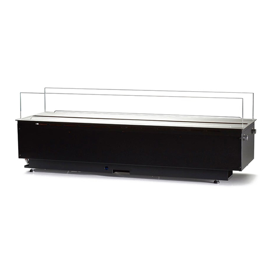
User Manual
MISTERO
for connection to water supply
The product complies with the European Safety Standards EN60335-2-30 and the European Standard Electromagnetic
Compatibility (EMC) EN55014, EN60555-2 and EN60555-3. These cover the essential requirements of EEC Directives
2006/95/EC and 2004/108/EC
1
Advertisement
Table of Contents

Related Manuals for safretti Magic-Fire MISTERO 500

Summary of Contents for safretti Magic-Fire MISTERO 500
- Page 1 User Manual MISTERO for connection to water supply The product complies with the European Safety Standards EN60335-2-30 and the European Standard Electromagnetic Compatibility (EMC) EN55014, EN60555-2 and EN60555-3. These cover the essential requirements of EEC Directives 2006/95/EC and 2004/108/EC...
-
Page 2: Table Of Contents
Index Safretti Mistero 500, Mistero 1000…………………………………………………………………………………2 Introduction…………………………………………………………………………………………………….2 Important Safety Advice…………………………………………………………………………………………….2 General Information………………………………………………………………………………………………...3 Installation Instructions………………………………………………………………………………………………3 Building the product surround/enclosure……………………………………………………………………..4 Ventilation……………………………………………………………………………………………………...5 Water connection……………………………………………………………………………………………..6 Electrical connection…………………………………………………………………………………………..7 Installing the product into surround/enclosure……………………………………………………………….8 Commissioning/initial product start-up………………………………………………………………………...9 Multiple product installation (daisy chaining)………………………………………………………………...10 Operating the product……………………………………………………………………………………………15 Manual controls………………………………………………………………………………………………15 Receiver contols……………………………………………………………………………………………...16... -
Page 3: Safretti Mistero 500, Mistero 1000
Safretti Mistero 500, Mistero 1000 Introduction Please read this information guide carefully to be able to safely install, use and maintain your product. Important Safety Advice When using electrical appliances, basic precautions should always be followed to reduce the risk of fire, electrical shock and injury to persons, including the following: If the appliance is damaged, check with the supplier before installation and operation. -
Page 4: General Information
The appliance carries a DO NOT COVER warning symbol. This appliance is not equipped with a device to control the room temperature. Do not use this appliance in small rooms when they are occupied by persons not capable of leaving the room on their own, unless constant supervision is provided. -
Page 5: Building The Product Surround/Enclosure
Water Connection Please ensure a water connection is located within 1m of the product. The water connection should be one of the following: A male ¾ inch BSP connection (same as a standard supply for a washing machine) A male ½ inch BSP connection (Fig. 5.1) Both the water and electrical connections should be accessible during product installation so that the connections can be made to the product easily. -
Page 6: Ventilation
You are required to leave a minimum of 400 mm from the base of the fuel bed to any shelf/enclosure above the product (Fig. 2). This will allow enough space above the product to allow the flame effect to form fully and not to be obstructed. When determining a location for the product, ensure that the unit will not be susceptible to drafts, vents, ceiling fans and other air currents. -
Page 7: Water Connection
If the ventilation openings are covered, for example by a ventilation grill, the effective ventilation, as mentioned above, will be reduced. So in that case there needs to be created extra ventilation! This must be taken into account in advance, so that the minimum requirements for ventilation are maintained! WATER CONNECTION It is recommended that you consult a qualified plumber to ensure a safe and secure installation. -
Page 8: Electrical Connection
ELECTRICAL CONNECTION Plug the fire into a 16amp/230 Volt outlet. Be sure to have access to the plug after installation to allow for disconnection. Ensure that the supply cable exits at the back of the fire at the right or left hand corner to suit your supply socket location and is not trapped under the fire such that it might cause it to be damaged. -
Page 9: Installing The Product Into Surround/Enclosure
4. Unscrew and remove the Live, Neutral and Earth wires (Fig. 7A). 5. Unscrew the cable clamp (Fig. 7B) and remove the supply cord. 6. The electrician can then connect the wire from the appliance to the connection box (by following the steps above in reverse) ensuring that it incorporates a double pole isolating switch, having a contact separation of at least 3 mm. -
Page 10: Commissioning/Initial Product Start-Up
4. With the product in its final position, remove the top plate and screw the product to the surround using the four fixing holes shown in Fig. 11. COMMISSIONING/INITIAL PRODUCT START-UP Connecting the Receiver/Tethered Remote Insert the 3.5 mm jack of the Bluetooth receiver into the socket at the back of the appliance (Fig. 12). It is important to ensure that the jack is pushed fully into the socket. -
Page 11: Multiple Product Installation (Daisy Chaining)
Initial Product Start-up In some cases, where low water pressure exists or where the product is being fed by the pump accessory, the product may start to fill with water but not complete its first fill within the allowed filling time period. It is recommended that each sump is primed with 600-700 ml of water before switching on the product for the first time. - Page 12 1. When the first product is installed and securely fixed, prepare the second product by unscrewing the joining screws (Fig. 20A) and screwing them into the opposite side of the metalwork (Fig. 20B). Please note, these screws should not be fully tightened and 5-10 mm of thread should be left protruding from the edge of the product.
- Page 13 The levelness of the product can be verified by checking the on-board level (Fig. 9). 4. Tighten the screws of the second product so that it joins tightly with the first product. Additional product scan be fitted to the second product by following steps 1-4 above. Multiple Product Control Each product has been supplied with its own link wire in order to form a hardwire link between the multiple products.
- Page 14 This will be the only Bluetooth receiver in the installation and will control the rest of the products in the installation. In an installation of both M500 and M1000 products, a M500 receiver (Fig. 12) should be connected to the ‘master’ product. 3.
- Page 15 5. For a M500, plug the link wire into the 3.5 mm jack housed in the plastic (Fig. 25). For a M1000 plug the link wire into the 3.5 mm jack housed in the plastic on the left hand side module (Fig. 26). 6.
-
Page 16: Operating The Product
Additionally, the software of the product has been designed in such a way that when multiple products are connected to a main switch, products can be manually switched off and when switched back on they will operate in the same state as before they were switched off. Operating the Product This section describes how to activate your fire using either the manual controls or remote control. -
Page 17: Receiver Contols
M1000 Mains Switch: Controls the electricity supply to the appliance. (Fig. 27A). Note: This switch must be in the ‘ON’ ( I ) position for the appliance to operate. Button Panel ‘C’ controls the functioning of the left side of the product while Button Panel ‘D’ controls the functioning of the right side of the product. - Page 18 M500 • is the on/standby button. Press it to turn on and off the flame effect. • is used to mute the fire crackling sound. Press this to turn on and off the crackling sound. The volume can be adjusted on the manual controls of the appliance. Please note that the mute setting will not be saved after a product restart.
-
Page 19: Remote Control
REMOTE CONTROL The remote control is supplied with 2x AAA-batteries. Remove the battery cover from the underside of the remote control and fit them into place, taking note of the correct orientation of the batteries. Replace the battery cover. Once the batteries have been inserted, ‘Pair’ will be displayed on the remote screen for a period of 30 seconds. - Page 20 2. Switch on the main switch of the product (Fig. 27A). An audible beep will be heard and the product will start advertising its Bluetooth signal for a period of 30 seconds. 3. Now press the arrow Left & Right at the remote control at the same time until Fry will be displayed. Press Enter, ‘Pair’...
- Page 21 Setting the Date and Time for the First Time When first setting up the remote control, you will be presented with the time and date set up screen before you can begin to use the remote control. Follow the steps below to set up the time and date for the remote control. (Note, the time on the remote control will be represented in the 24-hour clock format and cannot be changed.) 1.
- Page 22 4. Once selected, follow steps 2-14 above to set the day and time. Operating the Remote Control Note, in order to lengthen battery life, the remote control will enter sleep mode if no button is pushed for 15 seconds. In order to ‘wake’ the remote, press and hold ‘Button 6 – Enter’ for two seconds. Switching the Product On/Off 1.
- Page 23 Setting the Flame Height 1. When on the home screen, push ‘Button 5 – Arrows’ to navigate up to the ‘Fire’ icon at the top of the screen (Fig. A). 2. When the ‘Fire’ icon is flashing, press ‘Button 6 – Enter’ to enter the flame height adjustment menu (Fig. 3.
- Page 24 Setting up the 7-day timer The product can be set up to turn on/off over four different time periods over seven days of the week. 1. When on the home screen, push ‘Button 5 – Arrows’ to navigate to the Timer icon at the bottom left of the screen (Fig.
- Page 25 Copying On/Off Timers to Different Days The four time periods that have been set for a particular day can be copied to other days. 1. When on the home screen, push ‘Button 5 – Arrows’ to navigate to the Timer icon at the bottom left of the screen (Fig.
- Page 26 3. If the current time corresponds to an inactive time period, the current time will be shown along with a flashing ‘Off’ symbol (Fig. D). The product will switch on at the next preset ‘On’ time period. Select the flashing ‘Off’ symbol using ‘Button 6 – Enter’ to switch off the timer. Resetting Product Errors The remote control can be used to reset some product errors.
-
Page 27: Getting The Desired Flame Effect
GETTING THE DESIRED FLAME EFFECT 1. Switch the appliance on by pressing the main switch to the on position and pressing the button. The flames will start after 45 seconds. 2. Press the buttons to adjust the flame to your desired level. Please give the product time to react to the changes you make. -
Page 28: Sump
Sump 1. Press Switch ‘A’ to the ‘OFF’ (0) position (Fig. 27). 2. Gently lift off the top plate and place it aside. 3. Disconnect the ‘fill cap’ by turning it clockwise until it clicks out of the locked position (Fig. 29). Lift it out and rotate the pipe and connections so that the fill cap is placed out of the way of the sump. -
Page 29: Transducer
The transducer is a consumable item and may need to be replaced through time, depending on its usage. Replacement transducers can be purchased from Safretti (info@safretti.com). The transducer is fixed in the sump with a plastic clip. If you need to replace your transducer: 1. -
Page 30: Changing The Leak Prevention Valve Pad
CHANGING THE LEAK PREVENTION PAD A leak prevention valve has been fitted to the appliance as an additional safety measure (Fig. 35). In the unlikely event that a leak occurs inside the product, the valve will prevent water from flowing to the product. When the valve has been activated, the pad within the valve absorbs water and expands, shutting off the valve. -
Page 31: Additional Information
Additional Information AFTER SALES SERVICE Your product is guaranteed for two years from the date of purchase. Within this period, we undertake to repair or exchange this product free of charge (excluding transducer discs & subject to availability) provided it has been installed and operated in accordance with these instructions. - Page 32 Product will not Cd57 Time from max level to min Ensure that there are no leaks in the operate. LEDs level is too short. sump. continuously blink Ensure that the floats are moving freely three times. Conflicting water level within the sump. readings (min and max level Ensure that the product is level.
Need help?
Do you have a question about the Magic-Fire MISTERO 500 and is the answer not in the manual?
Questions and answers