Table of Contents
Advertisement
Quick Links
114-94163-2
Application
Specification
09ARP2018 Rev C
Class 1
VEHICLE CHARGE INLET acc.
IEC62196-2 Type II
Fahrzeugladedose gemäß
IEC62196-2 Typ II
©2011 Tyco Electronics Corporation, a TE Connectivity Ltd. Company
1 of 20
All Rights Reserved
| Indicates Change
LOC B
*Trademark. TE Connectivity, TE connectivity (logo), and TE (logo) are trademarks. Other logos, product and/or Company names may be trademarks of their respective owners.
Advertisement
Table of Contents

Related Manuals for TE Connectivity IEC62196-2 Type II


Summary of Contents for TE Connectivity IEC62196-2 Type II
- Page 1 ©2011 Tyco Electronics Corporation, a TE Connectivity Ltd. Company 1 of 20 All Rights Reserved | Indicates Change LOC B *Trademark. TE Connectivity, TE connectivity (logo), and TE (logo) are trademarks. Other logos, product and/or Company names may be trademarks of their respective owners.
-
Page 2: Table Of Contents
Content / Inhalt ..........................3 Processing Note / Verarbeitungshinweis ..................3 APPLICABLE DOCUMENTS / Anwendbare Unterlagen ..............3 TE Connectivity Documents / TE Connectivity Unterlagen ............3 General Documentation / Allgemeine Unterlagen ................ 5 Application Tools / Verarbeitungswerkzeuge ................. 6 ASSEMBLY INSTRUCTIONS / Verarbeitungsrichtlinie .............. -
Page 3: Scope / Anwendungsbereich
Spezifikation. Im Falle des Widerspruches zwischen dieser Spezifikation und der Produktzeichnung oder des Widerspruches zwischen dieser Spezifikation und den aufgeführten Unterlagen hat die Produktspezifikation Vorrang. TE Connectivity Documents / TE Connectivity Unterlagen Customer drawings for Type 2 / Kundenzeichnungen für Typ 2 114-94163-2... - Page 4 114-94163-2 2177804 ACTUATOR, LOCKING UNIT, ASSY ZSB Aktuator mit Halter und Notentriegelungshebel 2177790 CABLE FIXATION, TE, Cover Inlet Kabelabgang UT 2177791 INSULATION COVER, TE, Cover Inlet Kabelabgang OT 2177861 FAMILY SEAL, MIXED Familiendichtung 1241473 Screw 3x20mm Schraube 3x20mm 2177810 PIN DIA 6.0, L/N, ASSY ZSB L, N Pin 2177812 PIN DIA 6.0, PE...
-
Page 5: General Documentation / Allgemeine Unterlagen
114-94163-2 General Documentation / Allgemeine Unterlagen Cable Specifications of Prescribed Cables / Leitungsspezifikation der vorgeschriebenen Leitungen Cross-section / Querschnitt 2 x 4,0mm² Supplier / Lieferant: Gebauer & Griller Kabelwerke GmbH Outer Diameter / Außendurchmesser 10,1 -0,6 Cable description / Leitungsbezeichnung: FLR31YBC11Y 2x4,0 (0,20) /T125 /3 Gebauer &... -
Page 6: Application Tools / Verarbeitungswerkzeuge
114-94163-2 APPLICATION TOOLS / VERARBEITUNGSWERKZEUGE Required application tools are / Benötigte Verarbeitungswerkzeuge sind: Application Parts Wire Size Crimp Hight H Die Set Nr.: Tool Nr.: Leitungs- Crimp Höhe H Matritze-Nr: Anschlag-WZ- Verarbeitungselemente querschnitt 4,0mm² 2,81mm +/-0,05 1-1105852-8 Pin Contact 0,75mm² 1,90mm +/-0,05 1-1105850-8 Stift Kontakt... -
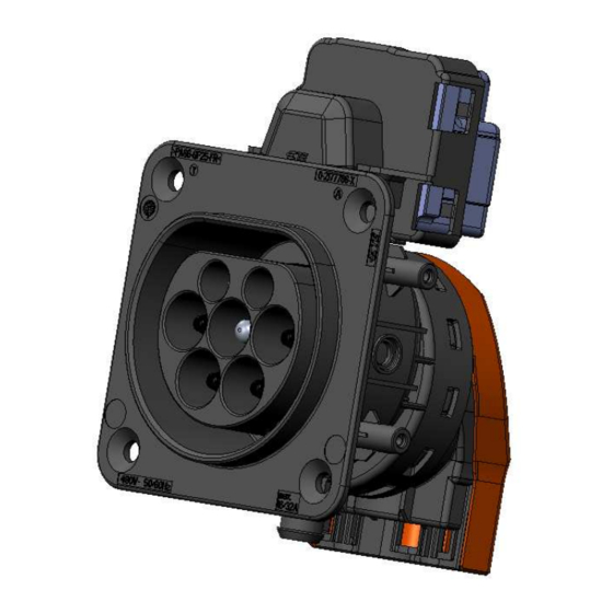
Page 7: Assembly Instructions / Verarbeitungsrichtlinie
114-94163-2 ASSEMBLY INSTRUCTIONS / VERARBEITUNGSRICHTLINIE Assembly overview / Baugruppenübersicht Figure / Bild 2 Charge Inlet Type II / Ladedose Typ II Rev C 7 of 20... -
Page 8: Parts To Order / Bestellteile
114-94163-2 Parts to order / Bestellteile Charge Inlet Type II / Ladedose Typ II L/N + Earth: L/N + Earth: Wire Size 4,0 mm² 6,0 mm² Leitungsquerschnitt Part Signal 0,75mm² Signal 0,75mm² Teil Pos. Qty. Name / Bezeichnung 7POS, MIXED, HSG, IEC62196-2 Type 2 0-2177786-1/-3/-5/-7 (1-phase) Ladedose Typ 2 0-2177786-2 (3-phase) -
Page 9: Security Advice / Sicherheitshinweis
114-94163-2 Security Advise / Sicherheitshinweis ATTENTION! - HIGH VOLTAGE APPLICATION - CABLE INSULATION MUST NOT BE DAMAGED! ACHTUNG ! - HOCHSPANNUNGSANWENDUNG - LEITUNGSISOLATION DARF NICHT BESCHÄDIGT WERDEN! The assembly shall only be performed by trained personnel. Die Montage ist nur von geschultem Personal durchzuführen. Avoid prolonged or repeated skin contact with silver plating (wear protective gloves)! Länger andauernden / wiederholten Hautkontakt mit den versilberten Oberflächen vermeiden (Schutz- handschuhe tragen)! -
Page 10: Assembly Steps / Montageschritte
114-94163-2 Assembly Steps / Montageschritte The assembly is shown for Type II Vehicle Charge Inlets. The assembly shall be done by trained personnel only! Die Assemblage ist dargestellt für Typ II Fahrzeugladedosen. Die Assemblage darf nur durch geschultes Personal erfolgen! Step 1 / Schritt 1 Assemble the Cable Fixation 2177790 to the Charge Interface at the required angle (see 114-94163- 2) by pressing the ring of the Cable Fixation into the related collar of the housing. - Page 11 114-94163-2 Step 2 / Schritt 2 The family seal 2177861 must be placed into the CABLE FIXATION 2177790 and into the INSULATION COVER 2177791. Ensure correct orientation of the seal (Figure 4). Die Familiendichtungen sind in die Teile Kabelabgang UT 2177790 und Kabelabgang OT 2177791 einzulegen.
- Page 12 114-94163-2 Figure / Bild 5 Step 5 / Schritt 5 Crimp the conductors to the contact pins with the specified tools. Care shall be taken that all braids are caught in the crimp. Not inserted braids may jeopardize HV requirements! Wires shall be completely inserted to be visible through the inspection hole (Figure 6).
- Page 13 114-94163-2 Step 7 / Schritt 7 Insert the Contacts from the backside into the Charge Inlet Housing according to the cavity description (figure 8) into their locking position. To ensure that the contacts are correctly inserted, pull and push with a low force on the cables (max. 10N) and check visually on the front side that the locking lances are properly engaged in the related pin groove.
- Page 14 114-94163-2 Backside / Rückseite Frontside / Vorderseite Figure / Bild 9 Step 8 / Schritt 8 Place the cables at their particular position into the CABLE FIXATION 2177790 and secure them with cable binders (Figure 10). Wire PE/Earth Left cable exit Power Multicore Cable ...
- Page 15 114-94163-2 Figure / Bild 10 Step 9 / Schritt 9 After the contacts have been controlled for correct positioning and locking, the Secondary Lock has to be pressed in from the frontside (figure 11). The adequate locking must be ensured and checked (dimensional check of correct position (figure 11).
- Page 16 114-94163-2 Figure / Bild 11 Figure / Bild 12 Rev C 16 of 20...
- Page 17 114-94163-2 Step 10 / Schritt 10 Assemble the Temperature Sensors into the Charge Inlet (Figure 13) in the related cavities. Press- in force may be applied on the brass collar ONLY. Push the sensor with the brass collar down to the bottom of the housing.
- Page 18 114-94163-2 Figure / Bild 14 Step 12 / Schritt 12 Assemble the Connector Locking Unit at the required position to the charge inlet. Ensure the prepositioning collar engages properly into the charge interface housing and fix the locking unit with two screws, torque 0,9 +/- 0,15 Nm (Figure 15). Die Stecker Verriegelungseinheit an der erforderlichen Position auf das Ladedosengehäuse montieren.
-
Page 19: End Of Line Test / Endprüfung
114-94163-2 End of Line Test / Endprüfung Assembled Charge Interfaces have to be tested electrically and mechanically to applicable requirements, including High Voltage test. As a minimum following tests have to be performed: Isolation Resistance: Test Voltage: 500VDC pin-to-pin (all pins, excluding CP-to-PP) Inspection Duration: 1s min. - Page 20 TYCO ELECTRONICS AMP GMBH 05DEC2013 A TE CONNECTIVITY LTD. COMPANY AMPÈRESTRAßE 12-14 D-64625 BENSHEIM F. WITTROCK GERMANY 05DEC2013 A. KETTELER 114-94163-2 05DEC2013 VEHICLE CHARGE INLET acc. IEC62196-2 Type II TITLE Fahrzeugladedose gem. IEC62196-2 Typ II Rev C 20 of 20...
Need help?
Do you have a question about the IEC62196-2 Type II and is the answer not in the manual?
Questions and answers