Table of Contents
Advertisement
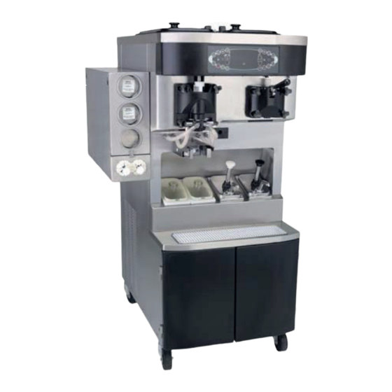
Soft Serve/Shake Combination Freezer
Taylor Model C602
Place this chapter in the Shakes/Desserts
section of the Equipment Manual.
Manufactured exclusively for
®
by
McDonald's
Taylor Company
750 N. Blackhawk Blvd.
Rockton, IL 61072
Phone: (815) 624-8333
Toll Free Number
Outside Illinois:
1 (800) 228-8309
Inside Illinois:
1 (800) 851-5639
Fax: (815) 624-8000
Table of Contents
Introduction ....................................................................................................................................................... 1
Safety ................................................................................................................................................................ 1
Parts Identification/Functions ............................................................................................................................ 4
Important To The Operator................................................................................................................................ 31
Daily Opening Procedures .............................................................................................................................. 34
Syrup System.................................................................................................................................................. 39
Daily Closing Procedures................................................................................................................................ 42
Scheduled Maintenance - Syrup System ........................................................................................................ 46
Syrup Topping Pump ...................................................................................................................................... 49
Manual Brush-Cleaning .................................................................................................................................. 54
Equipment Setup ............................................................................................................................................ 59
Vfd Screens................................................................................................................................................... 74
Manager's Menu ............................................................................................................................................. 78
Troubleshooting Guide.................................................................................................................................... 91
Parts Replacement Schedule ....................................................................................................................... 106
Limited Warranty On Equipment.................................................................................................................... 107
Limited Warranty On Parts ............................................................................................................................ 109
Ordering/Service Information ........................................................................................................................ 112
Warranty
Warranty information is contained in this Equipment Manual. Refer to the warranty information listed in the Limited Warranty on
Equipment and Limited Warranty on Parts sections and to the warranty classifications listed in the Parts Identification/Function
section when service is performed on your machine.
It is recommended that the operator take the necessary time to carefully read through the complete warranty information.
Thoroughly understand your warranty protection before you begin operation.
For any questions pertaining to the Taylor warranty, please contact Taylor Company, Rockton, Illinois 61072.
This manual is for the exclusive use of licensees and employees of McDonald's Corporation
©2005 McDonald's Corporation
All Rights Reserved
May, 2005 (Original Publication)
(Updated August, 2020 )
EM SD11
.
The United States of America
Printed in
Advertisement
Table of Contents

Related Manuals for McDonald's C602

Summary of Contents for McDonald's C602
- Page 1 Thoroughly understand your warranty protection before you begin operation. For any questions pertaining to the Taylor warranty, please contact Taylor Company, Rockton, Illinois 61072. This manual is for the exclusive use of licensees and employees of McDonald's Corporation ©2005 McDonald's Corporation...
- Page 3 INTRODUCTION SAFETY The Model C602 is a combination shake and soft serve Always follow these safety precautions when operating freezer. The soft serve side uses a 3.4 qt. (3.2 L) freezing the freezer: cylinder with a single-spout door. The shake side has a 7 qt. (6.6 L) freezing cylinder with a four-flavor dispensing door.
- Page 4 with a power cord and a plug or another device to disconnect the machine from the power source must have an all-pole disconnecting WARNING! DO NOT attempt to draw product device with a contact gap of at least 0.125 in. or disassemble the machine during the heat treatment (3 mm) installed in the external installation.
- Page 5 CAUTION! This machine is designed to IMPORTANT! A backflow prevention device is maintain product temperature under 41°F (5C). Any required on the incoming water connection side. Please product being added to this machine must be below 41F see the applicable national, state, and local codes for (5C).
- Page 6 PARTS IDENTIFICATION/FUNCTIONS Exploded View Warr. Item Part No. Description Qty. Function Class X65368 Kit A.-Cover-Hopper *Single* Protects mix in mix hopper from debris and helps keep Black temperature in the mix hopper uniform. X65178 Kit A.-Cover-Hopper *Dual* Note: If both hopper covers need to be replaced, order Black X65178.
- Page 7 C602 Exploded View Figure-1...
- Page 8 Front View Warr. Item Part No. Description Qty. Function Class 055987 Stud-Nose Cone Freezer door sits on these studs. Handscrews hold door in place. 056674 Fitting-Panel Mount QD Quick disconnect fitting for door syrup line. 068394 Clip-Spring Cup Holder Holds the cup in place during dispensing. X59304 Line A.-Syrup Door Delivers syrup to the freezer door.
- Page 9 Front View Figure-2...
- Page 10 Syrup Cabinet View Warr. Item Part No. Description Qty. Function Class 056016 Shelf-Syrup Provides access to syrup pumps. 059144 Basket-Door-Wire Rack for storage. 065933 Handle-Door Short Handle for syrup cabinet door. 058613 Block-Hinge Attaches door to syrup cabinet. 058322 Screw 8-32 X 1/2 Socket Hd Secures block hinge.
- Page 11 Mix Pump & Tubes Warr. Item Part No. Description Qty. Function Class 052916 Pump-Peristaltic Contains rollers to propel syrup. X54978 Kit A.-Peristaltic Pump Tube Compressed by pump rollers to propel syrup. 053036 Ferrule-.625 ID 2 ea. Clamps syrup hose on fitting. 054526 Fitting-Peristaltic Pump 2 ea.
- Page 12 X57028-XX Pump A. - Mix Simplified - Shake Warr. Item Part No. Description Qty. Function Class 1 - 7 X57028-XX Pump A.-Mix Simplified Shake Delivers air and mix to the freezing cylinder. 057944 Cylinder-Pump- Hopper-Shake Chamber to house the piston. X55450 Pin-Retaining Secures adaptor and valve cap in cylinder.
- Page 13 X57028-XX Pump A. - Mix Simplified - Shake Figure-5...
- Page 14 X57029-XX Pump A. - Mix Simplified - Soft Serve Warr. Item Part No. Description Qty. Function Class 1 - 7 X57029-XX Pump A.-Mix Simplified Delivers air and mix to freezing cylinder. Soft Serve 057943 Cylinder-Pump- Hopper-Soft Chamber to house the piston. Serve X55450 Pin-Retaining...
- Page 15 X57029-XX Pump A. - Mix Simplified - Soft Serve Figure-6...
- Page 16 Mix Hopper - Top View Warr. Item Part No. Description Qty. Function Class X44761 Sleeve A.-Mix Pump Hub used to hold the air/mix pump in a locked position. X41348 Probe A.-Mix Out Electrical device to indicate level of mix in the hopper.
- Page 17 X56652 Syrup Line Assembly - Triple Thick Shake Syrup Warr. Item Part No. Description Qty. Function Class 053036 Ferrule-.625 ID Clamps syrup hose on fitting. 056675 Insert-QD-CPC-3/8 Barb Connects syrup lines to front panel. Plastic 500205 O-ring Provides seal for quick disconnect fitting. 053052-9 Hose-Beverage 3/8 ID x 5/8 Delivers syrup to freezer door (9”).
- Page 18 X59304 Syrup Line Assembly - Thin Viscosity Syrup Warr. Item Part No. Description Qty. Function Class 029834 Ferrule-.650 ID Clamps syrup hose on fitting. 056675 Insert-QD-CPC-3/8 Barb Connects syrup lines to front panel. Plastic 500205 O-ring Provides seal for quick disconnect fitting. 500038-9 Tube-Vinyl Delivers syrup to freezer door (9”).
- Page 19 X58450 Syrup Line Assembly - Syrup-In-Bag Option Warr. Item Part No. Description Qty. Function Class 024278 O-ring-1/2 OD x .070 Provides a seal in the pump tube connection. 054526 Fitting-Male Peristaltic Connects to the pump tube. 053036 Ferrule-.625 ID NP Brass Secures the fitting on the hose.
- Page 20 Beater Door Assembly - Shake Side Warr. Item Part No. Description Qty. Function Class 032560 Seal-Drive Shaft Provides seal from product inside freezing cylinder to internal areas of freezer. 050985 Shaft-Beater 7 Qt. Fluted Connects beater assembly to gear unit. Blade 041103 Blade-Scraper-16”...
- Page 21 Beater Door Assembly - Shake Side Figure-11...
- Page 22 Beater Door Assembly - Soft Serve Side Warr. Item Part No. Description Qty. Function Class X56421-1 Handle A.-Draw Operational component of the draw valve assembly. 055989 Nut-Stud-Black Tightening mechanism to secure freezer door to freezing cylinder. X87683-1 Door A.-1SP 3.4QT Covers open end of freezing cylinder and Threadless provides port for the product to be dispensed.
- Page 23 Beater Door Assembly - Soft Serve Side Figure-12...
- Page 24 X53800-BRN/TAN Syrup Pump Warr. Item Part No. Description Qty. Function Class X53800-BRN Plunger A. Distributes and heats syrup toppings. X53800-TAN X36576-BRN Plunger A. Used to dispense toppings. X36576-TAN 032762-TAN Knob-Plunger Holds plunger assembly in place. TAN and BRN 032762-BRN indicate the hot caramel and hot fudge toppings. 032757 Tube-Plunger Guides plunger and plunger insert in place.
- Page 25 X53800-BRN/TAN Syrup Pump Figure-13...
- Page 26 Accessories Warr. Item Part No. Description Qty. Function Class X58474 Kit A.-Syrup Plug Kit Seals syrup ports in the shake door when the syrup valves are not installed. 053867 Plug-Syrup Port Seals syrup ports in the shake door when the syrup valves are not installed.
- Page 27 Item Part No. Description Qty. Function Class X49463-94 Kit A.-Tune Up C602 Blade Tune up kit containing: 1/X56200-10 pump kit, 1/X56200-12 draw valve kit, 1/X56200-13 shake door kit, 1/X56200-14 soft serve door kit, 1/X56200-15 syrup valve kit, 1/048260 O-ring removal tool,...
- Page 28 X44127 Brush Kit Assembly Warr. Item Part No. Description Qty. Function Class 013071 Black Bristle Brush To clean rear shell bearing and mix pump drive hub. 013072 Double End Brush To clean O-rings, holes in metal parts, piston grooves, mix inlet tube, mix inlet adapter, O-ring all grooves, draw valve core, valve caps, syrup line port holes in freezer door, syrup container feed tube, retaining pin, handscrew, pivot pin, and mix feed tube.
- Page 29 059088 Tray-Parts-Shake Side 16 15 Figure-16 Item Part No. Description Item Part No. Description X50958 Beater A.-7 Qt. X55820 Valve A.-Draw 041103 Blade-Scraper-16” X55820 Valve A.-Draw 050985 Shaft-Beater 7 Qt. 500598 Valve-Check Duckbill 032560 Seal-Drive Shaft 055605 Bearing-Door Front 055989 Nut-Stud 020571 O-ring - 1-1/16 OD...
- Page 30 059087 Tray-Parts-Soft Serve Side Figure-17 Item Part No. Description Item Part No. Description X56421-1 Handle A.-Draw X87683-1 Door Assembly 055819 Pin-Handle-SS 084108 Shoe-Front Helix- Front 087708 Baffle 032564 Drive Shaft 055989 Nut-Stud 032560 Seal-Drive Shaft 014402 O-ring (Draw Valve) 084350 Blade-Scraper 048926 Gasket (Freezer Door)
- Page 31 056525 Tray-Parts-Pump-Simplified Figure-18 Shake Side Item Part No. Description Item Part No. Description 044641 Clip-Mix Pump 054944 Adaptor-Mix Inlet Shake-Blue 057944 Cylinder-Pump- Hopper-Shake 056524 Ring-Check .120 OD X55450 Pin-Retaining X41947 Shaft A.-Drive Mix Pump 053526 Piston 048632 O-ring-Drive Shaft 044731 Pin-Cotter X55973 Tube A.-Feed- Hopper Shake...
- Page 32 056525 Tray-Parts-Pump-Simplified Cont. Soft Serve Side Item Part No. Description Item Part No. Description 044641 Clip-Mix Pump 054825 Adaptor-Mix Inlet Soft Serve-Red 057943 Cylinder-Pump- Hopper-Soft 056524 Ring-Check.120 OD Serve X41947 Shaft A.-Drive Mix Pump X55450 Pin-Retaining 048632 O-ring-Drive Shaft 053526 Piston X55974 Tube A.-Feed- Hopper Soft...
- Page 33 IMPORTANT TO THE OPERATOR Figure-19 Item Part No. Description Keypad-Shake For selecting operating functions on the shake side of the machine. Display-Vacuum Fluorescent Screen that displays menu options and notifies operator if a fault is detected. Menu (VFD) Keypad-Menu (Entry/Exit) To select the Manager's Menu or to exit the Menu Display.
- Page 34 Symbol Definitions Vacuum Fluorescent Display To better communicate in the international arena, the The vacuum fluorescent display (VFD) is on the front words on many of the operator keys have been replaced control panel. During normal operation the display is by symbols to indicate their functions.
- Page 35 Reset Mechanism Air/Mix Pump Reset Mechanism The reset button is in the service panel at the rear of the The reset button for the pump is in the service panel at machine. It protects the beater motor from overloading. the rear of the machine. (See Figure-20.) The reset Should an overload occur, the reset mechanism will trip.
- Page 36 Shake Fill Level Adjustment 3. Once the desired fill level is achieved, tighten the locknut. The portion control sensor is located under the cup holder. In front of the portion control sensor is the portion DAILY OPENING PROCEDURES control sensor shield. The sensor shield must be kept clean for the sensor to perform properly.
- Page 37 5. With the syrup-port brush, brush each syrup port hole ake Side 10 to 15 times. Dip the brush in sanitizing solution 1. When the Heating cycle is complete, the Heat cycle before brushing each port. (See Figure-25.) symbol will no longer be illuminated and the machine will automatically enter the Standby mode.
- Page 38 8. Install the restrictor cap on the freezer door spout. 11. Using the white end of the double-ended brush, (See Figure-27.) scrub the inside of the syrup nose fitting to remove any residual particles. ® 12. Using a shake cup filled with KAY-5 Sanitizer (HCS) solution, rinse the syrup nose fitting thoroughly.
- Page 39 17. Inspect the duckbill valve for proper installation inside The screen will display the Calibration Menu options. the syrup nose fitting. The tip of the duckbill valve (See Figure-33.) must be flat to seal the syrup line. (See Figure-31.) Figure-33 22.
- Page 40 25. When a steady stream of syrup is flowing from the syrup valve and all air has been purged from the syrup line, press any syrup Flavor symbol to stop the pump. 26. Repeat steps 23 and 24 to prime the rest of the syrup lines.
- Page 41 Soft Serve Side Note: This procedure should be performed 15 minutes prior to serving product. ® 1. Prepare a small amount of KAY-5 Sanitizer (HCS) SYRUP SYSTEM solution. Use one packet in 2.5 gal. (9.5 L) of water (100 ppm). Syrup Calibration 2.
- Page 42 The screen will display the Calibration Menu options. 5. To calibrate the syrup dispensing rate, hold the small (See Figure-43.) portion of the calibration cup under the valve for the flavor to be calibrated. Press the corresponding Flavor Selection symbol to activate the syrup pump and start the flow of syrup.
- Page 43 Syrup Priming Procedure 8. Press the Auto symbol or the optional Flavor symbol to scroll the arrow to SYRUP PRIME. Priming the syrup line eliminates any air in the syrup delivery system. Air in the syrup line can cause irregular (See Figure-49.) shake blending, flavor carryover, and syrup leaking from the door spout after the draw valve has closed.
- Page 44 DAILY CLOSING PROCEDURES 5. Place the restrictor cap, front drip tray, shake cup holder, and splash shield on a clean, dry surface to Note: This procedure must be done at the close of air-dry overnight or until the Heating cycle is business.
- Page 45 procedure should be performed for at least 10. Return to the freezer with a small amount of cleaning solution. With a pail below the door spout, dip the 10 seconds per port. (See Figure-57.) door-spout brush into the cleaning solution and brush-clean the syrup ports in the freezer door, door spout, bottom of the driven spinner, spinner blade, and syrup line fittings.
- Page 46 Soft Serve Side 16. Fill the squeeze bottle with sanitizing solution. Hold the bottle over a pail. Squeeze the bottle and Note: This procedure must be done at the close of thoroughly rinse the slot of each syrup nose fitting. business.
- Page 47 Important! Make sure your hands are clean and 10. Remove, clean, and re-install the long drip pan sanitized before continuing in these instructions. through the front panel. (See Figure-65.) Note: Select the Calibrate symbol to stop agitator movement for 10 seconds. Select the Calibrate symbol again to exit the Calibration mode.
- Page 48 A failure message will appear on the vacuum fluorescent 4. Raise the retainer and remove the syrup valve from display (VFD) to inform the operator that the machine did the freezer door. Place the valve in a pail located not successfully complete the Heat Treatment cycle. The under the draw valve.
- Page 49 13. Grasp the pump tube by both ends and remove it 6. Push down on the top of the pump to close it. from the pump body. (See Figure-68.) 7. Replace the pump cover tray and the syrup containers. 8. Prime the syrup lines. 9.
- Page 50 11. Remove the syrup nose fitting from the syrup valve by turning the cap counterclockwise. 12. Remove the duckbill valve and O-ring from the syrup nose fitting. 13. Using the white end of the double-ended brush, scrub the inside of the syrup nose fitting and the syrup line fitting to remove any residual particles.
- Page 51 30. Clean the syrup cabinet interior with a clean, 5. Remove the plunger nut, tube, and insert from the sanitized towel. Spray resistant areas with plunger assembly. (See Figure-74.) ® KAY-5 Sanitizer (HCS). SYRUP TOPPING PUMP Syrup Topping Pump Disassembly Before the first use and after use weekly, disassemble and clean the pump.
- Page 52 8. Remove the O-ring from the seal. (See Figure-77.) 12. Remove the discharge tube from the valve body by turning it counterclockwise. (See Figure-80.) Figure-77 9. Remove the discharge tube locknut by turning it Figure-80 counterclockwise and sliding it off the discharge tube. 13.
- Page 53 4. Insert the black shielded brush into the top side of the 7. Move the brush back and forth to scrub this inlet valve. Scrub this area, specifically around the passageway. Advance the brush completely and pull steel ball. (See Figure-82.) the brush out of the valve body.
- Page 54 Syrup Topping Pump Assembly After pump disassembly and cleaning is complete, assemble the pump. 1. Lubricate and install the seal O-ring into the seal. (See Figure-87.) Figure-89 5. Install the plunger nut onto the plunger tube. (See Figure-90.) Figure-87 2.
- Page 55 plunger assembly and tighten the knob by turning it 10. Install the discharge tube onto the smaller opening in clockwise. (See Figure-92) the valve body by aligning the flats on the discharge tube with the locking grooves on the valve body. Push down the discharge tube until it is seated in the valve body opening.
- Page 56 5. With a pail beneath the door spout, press the Wash and Mix Pump symbols and open the draw valve. To disassemble the Model C602, the following items will Note: Shake Side: Press any flavor selection be needed: symbol to open the draw valve.
- Page 57 8. Remove the locking clip, mix feed tube, pump clip, and the assembled air/mix pump. Place the parts in the parts tray. 9. Shake Side Only: Remove the syrup lines from the freezer door by raising the syrup valve retainers and pulling the valves straight out of the door.
- Page 58 7. Once the cleaner stops flowing from the door spout, 5. Remove the driveshaft seal from the driveshaft. 6. Remove the freezer door O-ring, front bearing, close the draw valve and press the Wash symbol retainer pins, and the draw valve spinner assembly. canceling the Wash mode.
- Page 59 10. Remove the pump driveshaft from the drive hub in the rear wall of the mix hopper. (See Figure-103.) Figure-104 Note: Remove the pump driveshaft from the drive hub in Figure-103 the rear wall of the mix hopper. (See Figure-105.) Remove the two small O-rings and one large ...
- Page 60 8. Remove the two short drip pans from the rear panel. Remove the two notched drip pans from the left and right side panels. Take them to the sink for cleaning. (See Figure-107.) Figure-108 5. Using the black brush, clean the drive hub openings in the rear wall of the mix hoppers.
- Page 61 EQUIPMENT SETUP Freezing Cylinder Assembly—Shake Side WARNING! Make sure the power switch is in the OFF position. Failure to follow this instruction may result in severe personal injury from hazardous moving parts. With the parts tray available for the shake side: 1.
- Page 62 4. If the blades are in good condition, place each scraper blade over the holding pins on the beater assembly. (See Figure-113.) Figure-115 7. Lubricate the outer diameter of the spinner shaft seal. Fill the cups on each end of the seal with lubricant. Figure-113 (See Figure-116.) Note: The holes in the scraper blade must fit over the...
- Page 63 Important! Inspect to see that the spinner shaft seal is correctly installed in the groove. A worn, missing, or improperly installed spinner shaft seal will cause product leakage out the top of the draw valve. 9. Lubricate the smaller end of the driven spinner. (See Figure-118.) Figure-120 12.
- Page 64 13. Install the shake freezer door. Position the freezer door on the four studs on the front of the freezing cylinder. Align the top of the draw valve with the valve lifter bracket. Install the handscrews (short handscrews at the bottom of the door). Tighten equally in a crisscross pattern to ensure the door is secured.
- Page 65 Freezing Cylinder Assembly—Soft Serve Side WARNING! Make sure the power switch is in the OFF position. Failure to follow this instruction may result in severe personal injury from hazardous moving parts. With the parts tray available for the soft serve side: 1.
- Page 66 5. Holding the rear blade on the beater, slide it into the freezing cylinder halfway. Install the front scraper blade over the front holding pin. (See Figure-132.) Figure-130 Important! Do not run the machine with a damaged blade. Failure to follow this instruction may result in damage to the freezing cylinder.
- Page 67 8. Slide the beater assembly the rest of the way into the freezing cylinder. Make sure the beater assembly is in position over the driveshaft by turning the beater slightly until the beater is properly seated. When in position, the beater will not protrude beyond the front of the freezing cylinder.
- Page 68 14. Insert the baffle rod through the beater in the freezing 16. Slide the long drip pan into the hole in the front panel above the syrup topping dispensers. cylinder. With the door seated on the freezer studs, install the handscrews. Tighten equally in a (See Figure-141.) crisscross pattern to ensure the door is secure.
- Page 69 Mix Pump Assembly 4. Insert the piston into the retaining pin hole end of the pump cylinder. (See Figure-146.) 1. Inspect the rubber and plastic pump parts. The O-rings, check rings, and gaskets must be in 100% good condition for the pump and entire machine to operate properly.
- Page 70 7. Insert the valve cap into the hole in the mix inlet Note: The head of the retaining pin should be at the top adapter. (See Figure-149.) of the pump when installed. 10. Assemble the feed tube assembly. Slide the check ring into the groove of the feed tube.
- Page 71 12. Lay the pump assembly, pump clip, cotter pin, and Note: For ease in installing the pump, position the ball agitator in the bottom of the mix hopper for sanitizing. crank of the driveshaft in the 3 o'clock position. (See Figure-154.) Sanitizing—Shake Side ®...
- Page 72 5. Install the air/mix pump assembly at the rear of the 11. Press the Wash symbol . This will cause the mix hopper. To position the pump on the drive hub, sanitizing solution in the freezing cylinder to come in align the drive slot in the piston with the drive crank of contact with all areas of the freezing cylinder.
- Page 73 Note: At the conclusion of a brush-clean the Auto and 19. Return to the freezer with a small amount of Standby buttons will be disabled until the user selects sanitizing solution. With a pail below the door spout, Wash mode. A message will appear on screen SEL dip the door-spout brush into the sanitizing solution WASH TO SANITIZE to remind the user.
- Page 74 3. Install the pump assembly at the rear of the mix 10. Press the Wash and Mix Pump symbols hopper. To position the pump on the drive hub, align close the draw valve. (See Figure-164.) the drive hole in the piston with the drive crank of the driveshaft.
- Page 75 12. Remove the cotter pin from the pump. Stand the mix feed tube in the corner of the mix hopper. Place the cotter pin in position in the outlet fitting of the pump. (See Figure-166.) Figure-167 3. Install the shake cup holder. (See Figure-168.) Figure-166 Note: You have just sanitized all the food contact surfaces of the freezer.
- Page 76 2. When the mix stops bubbling down into the freezing During the Initializing ..if the system detects corrupt data, the following display will alert the operator that the cylinder, remove the cotter pin from the outlet fitting control settings have changed (see Figure-171): of the mix pump.
- Page 77 Power Switch ON When the power switch is placed in the ON position, the WARNING! DO NOT attempt to draw product control panel touch keys become operative. The VFD will or disassemble the machine during the heat treatment be either blank or indicate that the machine has been cycle (if equipped).
- Page 78 Hard Lock—There are two causes of a hard lock failure: The FREEZER LOCKED message will remain on the display until the brush-clean requirements are fulfilled. 1. The brush-clean timer has elapsed (maximum setting The freezer must be disassembled in order to activate of 14 days).
- Page 79 If the following screen appears, soft lock has occurred during the Heat Treatment cycle (see Figure-185): Figure-188 To restore the message that identified the reason for the Figure-185 soft lock, turn the power switch OFF for 5 seconds, and A soft lock can also occur anytime during operation when then return the power switch to the ON position.
- Page 80 Optional Flavor -—decreases the value above the cursor and is used to scroll downward in text displays. Calibrate —advances the cursor position to the right and is used to select menu options. Note: You will not be able to dispense shakes while accessing the Manager's Menu options except when the CURRENT CONDITIONS screen is displayed.
- Page 81 The SYRUP CALIBRATION option allows the manager Reset the SERVINGS COUNTER by selecting the AUTO to access the calibration screen selections from the symbol to move the arrow to Next. The Reset Manager's Menu. The same functions found in the Counters and Details selections will be displayed on the Calibration menu are displayed on the screen when this next screen.
- Page 82 The Counter menu will also display details for the number Change the time by pressing the Auto or optional of servings for each flavor (chocolate, strawberry, vanilla, Flavor symbol with the cursor under the hour option, unflavored, and soft serve) and count the method position.
- Page 83 Use the arrow keys to scroll to the appropriate month. Note: Do not advance the AUTO HEAT TIME setting except on the day the machine is brush-cleaned. Press the Calibrate symbol to accept the selection. Increasing the time between Heat cycles will cause the (See Figure-206.) machine to soft lock if the start of the cycle does not begin within 24 hours from the start of the previous Heat...
- Page 84 Program the AUTO START TIME by selecting the Auto symbol to move the arrow to Change. Select the to advance to the next screen. Calibrate symbol (See Figure-214.) Figure-216 Change the number of days between brush-clean intervals by selecting the Auto symbol to decrease the days, or the optional Flavor symbol to increase...
- Page 85 The second line of the screen displays the date and time Select the Calibrate symbol to display the next fault a failure occurs. The third line indicates the reason for a found, or return to the Manager's Menu if no other faults failure, or if a successful brush-cleaning has occurred.
- Page 86 Faults Occurring While in Auto Mode: Fault Descriptions (L/R) HPR>41F (5C) AFTER 4 HR—The mix (L/R) Comp On Too Long—The left or right main temperature in the left or right hopper was above 41°F compressor has run for more than 11 consecutive (5°C) more than 4 hours.
- Page 87 The first screen displays the month and day of the Heat Select the Auto symbol to advance to the next page, cycle, the start time and end time, and the fault or the optional Flavor symbol to view the previous description.
- Page 88 The HEAT CYCLE DATA Details record the temperature With the arrow on the Display record line, select the in the freezing cylinders and mix hoppers every 5 Calibrate symbol . (See Figure-229.) minutes during the Heat Treatment cycle. Up to 366 Heat Treatment cycles are recorded.
- Page 89 Selecting the Calibrate symbol will advance the screen to the next zone. The second temperature zone displayed is the left barrel (LB). (See Figure-233.) Figure-238 Select the Calibrate symbol to view the Heat cycle results screen. (See Figure-239.) Figure-233 Select the Calibrate symbol to advance to the next temperature zone, the right hopper (RH).
- Page 90 The CURRENT CONDITIONS screen is the only menu For UVC4 models only, select the Calibrate symbol screen that will return the left and right side control panel advance to the third system information screen keys to normal operation. The menu keys will not be lit containing the Boot loader version.
- Page 91 For Machines Equipped with Taylor's Dispensing Shake Without Syrup Remote Monitoring System Beginning with software version 1.04, shakes can be dispensed without flavoring by selecting the left-side Mix FCC/IC ID Label Placement: Pump symbol . (See Figure-247.) • This hardware installation package includes a label that must be placed on the machine immediately after the installation of the hardware device has been completed.
- Page 92 TROUBLESHOOTING GUIDE Shake Side Soft Serve Side Either Side Probable Problem Corrective Action Probable Cause Probable Cause. Cause Soft lock message a. A machine fault has a. Determine the reason the failure occurred. Correct the appears on display. occurred. cause for failure, then select the Heat symbol to start a Heat cycle, or Wash to disassemble and brush-clean the machine.
- Page 93 Shake Side Soft Serve Side Either Side Probable Problem Corrective Action Probable Cause Probable Cause. Cause No product is being a. Low on mix, the Mix a. Add mix to the mix hopper. Return to Auto mode. dispensed. Out light is on. b.
- Page 94 Shake Side Soft Serve Side Either Side Probable Problem Corrective Action Probable Cause Probable Cause. Cause The product is too a. Too much syrup. a. Calibrate the syrups. soft. Non-TTS: 1 fl. oz. (30 ml) in 5 seconds. For triple thick shake syrup: 1 oz.
- Page 95 Shake Side Soft Serve Side Either Side Probable Problem Corrective Action Probable Cause Probable Cause. Cause The product is too a. Not enough syrup. a. Calibrate the syrups. Check that the syrup containers are thick. Non-TTS: 1 fl. oz. not empty. (30 ml) in 5 seconds.
- Page 96 Shake Side Soft Serve Side Either Side Probable Problem Corrective Action Probable Cause Probable Cause. Cause Excessive mix a. Bottom O-ring on the a. Lubricate properly or replace the O-ring. leakage from the draw valve is bottom of door spout. improperly lubricated or worn.
- Page 97 Shake Side Soft Serve Side Either Side Probable Problem Corrective Action Probable Cause Probable Cause. Cause The freezing cylinder a. Missing or worn a. Install or replace the front bearing. walls are scored. front bearing. b. Missing or worn b. Install or replace the front bearing and/or beater shoes. front bearing and/or beater shoes.
- Page 98 Shake Side Soft Serve Side Either Side Probable Problem Corrective Action Probable Cause Probable Cause. Cause Syrup toppings are a. Topping heaters a. Select topping heater symbols. Symbols will be lit when the not hot. are not on. heaters are on. b.
- Page 99 Shake Side Soft Serve Side Either Side Probable Problem Corrective Action Probable Cause Probable Cause. Cause Shake draw valve is a. The power switch a. Place the power switch in the ON position. not opening. is OFF. b. The shake side is b.
- Page 100 Shake Side Soft Serve Side Either Side Probable Problem Corrective Action Probable Cause Probable Cause. Cause Shake draw valve is a. The draw valve a. Re-assemble with the correct alignment. Tighten the not closing. was not aligned handscrews in a crisscross pattern when installing the with the actuator freezer door.
- Page 101 Shake Side Soft Serve Side Either Side Probable Problem Corrective Action Probable Cause Probable Cause. Cause Syrup cannot be a. The pump tube has a. Replace the pump tube. calibrated or has collapsed. inconsistent b. Syrup temperature b. Allow the syrup to warm up before using. Note: Never calibration readings.
- Page 102 Shake Side Soft Serve Side Either Side Probable Problem Corrective Action Probable Cause Probable Cause. Cause Spinner shaft will not a. Spinner motor is a. Allow the spinner motor to cool. Check lubrication on the rotate to blend mix out on thermal spinner shaft.
- Page 103 Shake Side Soft Serve Side Either Side Probable Problem Corrective Action Probable Cause Probable Cause. Cause Syrup flavor a. Draw handle was a. Allow the sensor to close the draw valve. Do not manually cross-over from closed manually. close the draw handle. previous shake.
- Page 104 Shake Side Soft Serve Side Either Side Probable Problem Corrective Action Probable Cause Probable Cause. Cause Shake not filling a. Cup improperly a. Place the cup in the holder with the lip resting on the clips. completely to top line placed in holder, in cup.
- Page 105 Shake Side Soft Serve Side Either Side Probable Problem Corrective Action Probable Cause Probable Cause. Cause Shake is filling too a. Sensor shield is a. Clean the sensor shield. high in cup. obstructed, unable to detect temperature change. b. Cup holder not b.
- Page 106 Shake Side Soft Serve Side Either Side Probable Problem Corrective Action Probable Cause Probable Cause. Cause Too much syrup a. Improper syrup a. Use correct calibration cup (Taylor part no. 017203) and flavoring in shake. calibration caused use the small chamber of the cup. by using incorrect syrup calibration cup.
- Page 107 PARTS REPLACEMENT SCHEDULE Every 3 Every 4 Part Description Every 6 Months Annually Months Years Door Assembly-Shake and Soft Serve Scraper Blade-Shake Scraper Blade-Soft Serve Driveshaft Seal Freezer Door O-ring-Shake Freezer Door Gasket-Soft Serve Front Bearing Front Beater Shoes-Soft Serve Draw Valve O-ring Spinner Shaft Seal-Shake Restrictor Cap-Shake...
- Page 108 Taylor, through an authorized Taylor distributor or service agency, will provide a new or remanufactured part, at Taylor’s option, to replace the failed defective part at no charge for the part. Product Part Limited Warranty Period C602 Insulated shell assembly Five (5) years Refrigeration compressor (except service valve) Five (5) years...
- Page 109 7. Failure, damage, or repairs due to faulty installation, misapplication, abuse, no or improper servicing, unauthorized alteration, or improper operation or use as indicated in the Equipment Manual, including but not limited to the failure to use proper assembly and cleaning techniques, tools, or approved cleaning supplies. 8.
- Page 110 LIMITED WARRANTY ON PARTS TAYLOR COMPANY LIMITED WARRANTY ON TAYLOR GENUINE PARTS Taylor Company is pleased to provide this limited warranty on new Taylor genuine replacement components and parts available from Taylor to the market generally (the “Parts”) to the original purchaser only. LIMITED WARRANTY Taylor warrants the Parts against failure due to defect in materials or workmanship under normal use and service as follows.
- Page 111 LIMITED WARRANTY EXCEPTIONS This limited warranty does not cover: 1. Labor or other costs incurred for diagnosing, repairing, removing, installing, shipping, servicing, or handling of defective Parts, replacement Parts, or new Parts. 2. Normal maintenance, cleaning, and lubrication as outlined in the Taylor Operator’s Manual, including cleaning of condensers or carbon and grease buildup.
- Page 112 LIMITATION OF WARRANTY THIS LIMITED WARRANTY IS EXCLUSIVE AND IS IN LIEU OF ALL OTHER WARRANTIES, CONDITIONS, AND/OR REMEDIES UNDER THE LAW, INCLUDING ANY IMPLIED WARRANTIES OR CONDITIONS OF MERCHANTABILITY OR FITNESS FOR A PARTICULAR PURPOSE. THE ORIGINAL OWNER'S SOLE REMEDY WITH RESPECT TO ANY PRODUCTS SHALL BE REPAIR OR REPLACEMENT OF DEFECTIVE PARTS UNDER THE TERMS OF THIS LIMITED WARRANTY.
- Page 113 Taylor compressor warranty. It is the unit owner's responsibility to make this fact known 1. Model Number: C602-HT to any technician he/she employs. It should also be noted that Taylor does not warrant the 2. Serial Number_________________________ refrigerant used in its equipment.
- Page 114 057888-M...
Need help?
Do you have a question about the C602 and is the answer not in the manual?
Questions and answers