Table of Contents
Advertisement
Quick Links
Advertisement
Table of Contents

Related Manuals for SPECS KolibriSensor

Summary of Contents for SPECS KolibriSensor
- Page 1 KolibriSensor Starter Kit User Manual V2.0 | June 17, 2014...
- Page 2 SPECS order number reference: 78000248 © 2014 . All rights reserved. No part of this manual may be reproduced without the prior per- mission of SPECS GmbH. Kolibri® and KolibriSensor® are registered trademarks of SPECS GmbH. Other product and company names mentioned in this document may be the trademarks or...
-
Page 3: Table Of Contents
Environmental Operating Conditions Chapter 2 – Installation Unpacking Electrical Connections Chapter 3 – Operation Inserting a KolibriSensor into the Test Stage Setting Up Oscillation Parameters Removing a KolibriSensor from the Test Stage Chapter 4 – Technical Details The KolibriPreamp Attenuators Receptor Pin Assignment KolibriSensor V2.0 | June 17, 2014... - Page 4 This page intentionally left blank. KolibriSensor V2.0 | June 17, 2014...
-
Page 5: List Of Figures
Figure 1: Parts supplied in Starter Kit delivery Figure 2: Electrical connections for the Starter Kit Figure 3: Removing the KolibriSensor from the holder Figure 4: Holding the sensor ready for insertion into the receptor Figure 5: Aligning the sensor into the receptor... - Page 6 This page intentionally left blank. KolibriSensor V2.0 | June 17, 2014...
-
Page 7: Chapter 1 - Introduction
Welcome to the user manual for the SPECS KolibriSensor Starter Kit. The Starter Kit enables evaluation of a KolibriSensor without the need to mount it in a micro- scope. The KolibriSensor has proven its qualities in the SPECS Aarhus SPM 150 and the SPECS JT-SPM as well as being suited for use in custom microscopes. - Page 8 There must be no condensed water on the equipment. Atmospheric pressure: Ÿ 800–1200 mbar Air conditioning is advisable in order to ensure the ambient requirements, especially for dis- sipating heat produced by the equipment. KolibriSensor V2.0 | June 17, 2014...
-
Page 9: Chapter 2 - Installation
In case of missing or damaged parts, please contact SPECS immediately. Figure 1: Parts supplied in Starter Kit delivery The SPECS KolibriSensor Starter Kit consists of the following components, as pictured in Figure 1: KolibriSensor V2.0 | June 17, 2014... -
Page 10: Electrical Connections
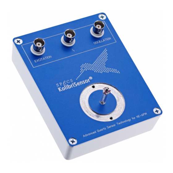
Oscillation Controller Figure 2: Electrical connections for the Starter Kit The I connector is connected to the tip of the KolibriSensor and is therefore not used for driv- ing the sensor oscillation. Caution! Make sure the attenuators are fitted as shown in Figure 2. These prevent pos- sible damage to the sensor induced by too high excitation amplitudes. -
Page 11: Chapter 3 - Operation
Inserting a KolibriSensor into the Test Stage The KolibriSensor is stored in a transport package when it is not in use. SPECS supplies a spe- cial pair of tweezers for handling the KolibriSensor. These are shaped so that they will correctly grip the KolibriSensor: this greatly simplifies the process of inserting and removing the sensor. -
Page 12: Setting Up Oscillation Parameters
Setting Up Oscillation Parameters The following procedure describes the normal operation of a KolibriSensor using the Starter Kit and the Nanonis Oscillation Controller. The resonant frequency and Q factor of the sensor are measured. The Nanonis Oscillation Controller is set up using typical oscillation parameters to drive the sensor oscillation at the resonant frequency with controlled amplitude. -
Page 13: Figure 6: Settings In The Oscillation Control Panel
Figure 6: Settings in the Oscillation Control panel 4. Set the following in the Oscillation Control panel (refer also to Figure 6): Ÿ Make sure Amplitude control is off. Ÿ Make sure Phase control is off. KolibriSensor V2.0 | June 17, 2014... -
Page 14: Figure 7: Signals In Frequency Sweep Panel
(PLL lock range) to a reasonably high value such as 1.22 kHz. fcenter Ÿ (PLL center frequency) to the resonance frequency of the KolibriSensor as given on the sensor’s specification sheet. Ÿ Make sure the output of the Oscillation Controller is switched on by unchecking the option box. -
Page 15: Figure 8: Altering The Sweep Range Or Number Of Points
Phase Controller BW Ÿ : 50 Hz Note FM-AFM measurements may require amplitude controller and phase controller bandwidths to be optimized according to specific requirements. The values indicated above may serve as a starting point. KolibriSensor V2.0 | June 17, 2014... -
Page 16: Removing A Kolibrisensor From The Test Stage
Removing a KolibriSensor from the Test Stage To remove the KolibriSensor from the test stage: 1. Remove the sensor by gripping it below the guidance ring with the tweezers and pulling it out of the KolibriReceptor. -
Page 17: Chapter 4 - Technical Details
Figure 12: KolibriPreamp The nominal conversion factor of the KolibriPreamp used with the KolibriSensor is 0.7 V/nm. This means that an oscillation amplitude of 1 nm of the oscillating KolibriSensor induces an out- put voltage from the KolibriPreamp of 0.7 V. -
Page 18: Attenuators
The Starter Kit is supplied with two 20 dB attenuators. These are connected in series between the output of the Nanonis Oscillation Controller and the Excitation input of the test stage. The attenuators protect the KolibriSensor from excessive drive levels and improve the signal to noise ratio of the excitation signal.
Need help?
Do you have a question about the KolibriSensor and is the answer not in the manual?
Questions and answers