Table of Contents
Advertisement
Quick Links
UVC-FRM01
Windows, Windows2000, Windows NT and Windows XP are trademarks of Microsoft. We acknowledge that the
trademarks or service names of all other organizations mentioned in this document as their own property.
Information furnished by DAQ system is believed to be accurate and reliable. However, no responsibility is assumed by DAQ
system for its use, nor for any infringements of patents or other rights of third parties which may result from its use. No license is
granted by implication or otherwise under any patent or copyrights of DAQ system.
The information in this document is subject to change without notice and no part of this document may be copied or
reproduced without the prior written consent.
User's Manual
Copyrights 2005 DAQ system, All rights reserved.
1-
-
UVC-FRM01 Users Manual (Rev 1.0)
http://www.daqsystem.com
Advertisement
Table of Contents

Subscribe to Our Youtube Channel
Related Manuals for DAQ system UVC-FRM01

Summary of Contents for DAQ system UVC-FRM01
- Page 1 Information furnished by DAQ system is believed to be accurate and reliable. However, no responsibility is assumed by DAQ system for its use, nor for any infringements of patents or other rights of third parties which may result from its use. No license is granted by implication or otherwise under any patent or copyrights of DAQ system.
-
Page 2: Table Of Contents
UVC-FRM01 Users Manual (Rev 1.0) -- Contents – 1. Introduction 2. UVC-FRM01 Function 2.1 Board Block Diagram 3. UVC-FRM01 Description Layout 3.1 UVC-FRM01 3.2 Components 3.3 Connector Pin-out 3.3.1 CN1 Connecter 3.3.2 J1 Connector 3.3.3 J4 Connecter 3.3.4 J5 Connecter 4. -
Page 3: Introduction
UVC-FRM01 Users Manual (Rev 1.0) 1. Introduction The UVC-FRM01 board receives digital or analog signals selected from HD-SDI (high-definiti on serial digital interface), NTSC (National Television System(s) Committee), and PAL (Phase Alt ernation Line) signals, and converts video data to UVC. Processed and transmitted with the (U SB Video Class) function. -
Page 4: Uvc-Frm01 Function
2. UVC-FRM01 Function 2.1 Board Block Diagram As shown in [Figure 2-1], in the case of UVC-FRM01, the overall control is in charge of FPGA Core Logic. Its main function is to receive video signals such as HD-SDI (high-definition serial digital interface), NTSC (National Television System(s) Committee), and PAL (Phase Alternation Line) through the external I/O connector to receive UVC (USB Video). -
Page 5: Uvc-Frm01 Description
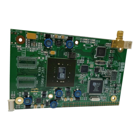
UVC-FRM01 Users Manual (Rev 1.0) 3. UVC-FRM01 Description 3.1 UVC-FRM01 Layout [Figure 3-1. UVC-FRM01 Layout] There are 6 important LEDs on the board, and the description of each is as follows. D2: Lights according to the setting of Analog(On), HD-SDI(Off). -
Page 6: Components
UVC-FRM01 Users Manual (Rev 1.0) 3.2 Components Briefly describes the functions of each board. Please refer to the parts specifications for detailed functions. (1) FPGA : U8 All functions of the board are controlled through this FPGA Logic. (2) UVC : U3 It provides USB Video Class. -
Page 7: Connector Pin-Out
UVC-FRM01 Users Manual (Rev 1.0) 3.3 Connector Pin-out The following describes the connector used in UVC-FRM01. 3.3.1 CN1 Connector This is an external HD-SDI signal line connector. 3.3.2 J1 Connector It is a 5V external DC power connector. 3.3.3 J4 Connecter J4 is a JTAG (Joint Test Action Group) connector that is used to update the FPGA program of the board. - Page 8 UVC-FRM01 Users Manual (Rev 1.0) Ground Not Connect Not Connect Ground Not Connect Not Connect Ground Not Connect Not Connect Ground Not Connect Not Connect Not Connect Not Connect Ground Ground SSRX- UVC Receiver Minus Not Connect SSRX+ UVC Receiver Plus...
- Page 9 UVC-FRM01 Users Manual (Rev 1.0) USB2.0 Plus Signal Ground Ground [Table 2. I2C Address Setting] HD-SDI Slave Slave Slave 0x20 0x20 0x04 Address Address Address 0x0A 0x08 0x20 Brightness Contrast Brightness 0x7f 0xff 0x28 0x79 0xf2 0x27 0x73 0xec 0x26...
- Page 10 UVC-FRM01 Users Manual (Rev 1.0) 0xd8 0x62 0x0f 0xd5 0x5c 0x0e 0xcf 0x56 0x0d 0xc9 0x50 0x0c 0xc3 0x4a 0x0b 0xbd 0x44 0x0a 0xb7 0x3e 0x09 0xb1 0x38 0x08 0xab 0x32 0x07 0xa5 0x2c 0x06 0x9f 0x26 0x05 0x99 0x20...
-
Page 11: Check The Contents
Check if My Computer -> Properties -> Hardware -> Device Manager screen, Imaging Device -> “UVC-FRM01 Frame Grabber” is installed. If it appears as shown in [Figure 4-1], the installation has been completed normally. (Check the red circle) [Figure 4-1. -
Page 12: Sample Program
UVC-FRM01 Users Manual (Rev 1.0) 5. Sample Program A sample program is provided on the CDROM provided with the board so that the board can be used easily. The executable file is FrameTest.exe. [Figure 5-1. Sample Program Execution Screen] (1) “Device” Selection CAM 1 ~ 3 can be selected. - Page 13 UVC-FRM01 Users Manual (Rev 1.0) (3) “Go” button Show the video captured by CAM. If you want to change the image image, you can select and apply Filter, brightness, and contrast. To switch to full screen mode, press "f" on the image screen.
- Page 14 UVC-FRM01 Users Manual (Rev 1.0) References 1. USB 3.0 System Architecture -- Don Anderson, USB SIG (www.usb.org) 2. Universal Serial Bus Specification -- Compaq/Intel/Microsoft/NEC, MindShare Inc. (Addison Wesley) 3. UVC-FRM01 Manual -- DAQ system http://www.daqsystem.com...
Need help?
Do you have a question about the UVC-FRM01 and is the answer not in the manual?
Questions and answers