Table of Contents
Advertisement
Quick Links
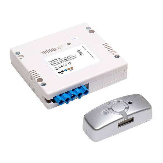
STOVE GUARD
STOVE GUARD
SGEL-SN-1
MAI N MAN UAL
Installation and Operating Instructions
1
INSTALLATION P. 4-13
For indoor use only.
Do not use in a professional kitchen.
The Control Unit must be installed by an authorized electrician.
SGEL-SN-1-UserManual-A1
2
USER GUIDE P. 14-23
3
TECHNICAL SPECIFICATIONS
P. 24-28
Advertisement
Table of Contents

Related Manuals for FireAngel SGEL-SN-1

Summary of Contents for FireAngel SGEL-SN-1
- Page 1 STOVE GUARD STOVE GUARD SGEL-SN-1 MAI N MAN UAL Installation and Operating Instructions INSTALLATION P. 4-13 USER GUIDE P. 14-23 TECHNICAL SPECIFICATIONS P. 24-28 For indoor use only. Do not use in a professional kitchen. The Control Unit must be installed by an authorized electrician.
- Page 2 • Do not disassemble the product. The operating instructions, accessories and stickers must accompany the product. Follow the safety rules for safe use of the Stove Guard. If you have questions about the product, ask a specialist or refer to FireAngel.co.uk...
-
Page 3: Table Of Contents
CONTENTS INSTALLATION 4-13 Installation of the Stove Guard Installation of Intelligent Heat Sensor Installation locations of Intelligent Heat Sensor 6-11 RECOMMENDED OPTIONAL Installation under cooker hood Wall mounting Ceiling mounting P. 6-7 P. 8-9 P. 10-11 Installation of Control Unit Function test USER GUIDE 14-23... - Page 4 Installing the Stove Guard To install correctly, follow the instructions. Temporrundia si auda STEP 1 : STEP 2 : STEP 3 : voluptatem facium fuga. Er- Installation of Installation of Function test chitatem aut omnis maximus Intelligent Heat Sensor the Control Unit dolessim que veliquas p.
-
Page 5: Installation
INSTALLATION OF INTEL L IG ENT HE AT SENSOR The best place to install the Intelligent Heat Sensor is horizontally, on the fan, directly above the middle of the cooker. The Sensor can also be mounted on a wall with an angle bracket or in the ceiling. One Sensor covers a cooker up to 90 cm wide. -
Page 6: Installation Locations Of Intelligent Heat Sensor
Select the mounting location Mount the Heat Sensor Measure the installation height. The Heat Sensor should be centred Attach the mounting plate while above the cooker, preferably within zone 1 (see the table). It can be the Sensor is on it. attached to the grease filter. - Page 7 COOKER HOOD H ORIZONTA L INSTA LL ATI ON UN DER C OO KER HO OD Allow the Heat Sensor to reach room temperature before use. The power to the cooker must be switched off (fuse box). See the table for the mounting location and follow the instructions from 1-4.
- Page 8 Select the mounting location and mount the bracket Mount the Heat Sensor Wall mounting requires a bracket, which is sold separately (see page Attach the mounting plate while 28). The bracket is fastened on the wall using adhesive tape or screws. the Sensor is on it.
- Page 9 WALL WALL MO UNTING WITH B R AC KE T Allow the Heat Sensor to reach room temperature before use. See the table and follow the instructions from 1-4. Starting the Sensor Set sensitivity level Remove the red battery discon- Set the Heat Sensor’s sensitivity level according to the table below.
- Page 10 Replace lens Select the mounting Mount the Heat Sensor location Carefully lift the lens with a Attach the mounting plate while screwdriver. Press down the the Sensor is on it. The sensor must be placed IR lens extension (included) directly above the cooker or as shown in the picture.
- Page 11 CEILING Allow the Heat Sensor to reach room temperature before use. See the table for the mounting location and follow the instructions from 1-5. Starting the Sensor Set sensitivity level Remove the red battery discon- Set the Sensor's sensitivity level to 1. See page 18. nection piece (B) and replace the Sensor on the mounting plate.
-
Page 12: Installation Of Control Unit
CONTROL UNIT I N STALL ATIO N O F C ONTROL UNIT It is a statutory requirement that the Control Unit is installed by an authorized electrician, except for plug & play versions. The power to the cooker must be disconnected during the entire installation. POWER Disconnect the power Switch off the power from the... -
Page 13: Function Test
FUNCTION TEST The installation is completed when the test has been passed. The Sensor will then give an alarm that can save lives and property. The operating instructions, accessories and stickers must accompany the product. POWER Return the power Perform function test Reset the alarm Connect the power. -
Page 15: Getting Started With The Stove Guard
LIESIVAHTI SGK510 LIESIVAHTI SGK510 OPAS KÄYTTÄJÄLLE OPAS KÄYTTÄJÄLLE GETTING STARTED Matalat asennuskorkeudet Matalat asennuskorkeudet Älylämpöanturi alle 90 cm lieden yläpuolella Älylämpöanturi alle 90 cm lieden yläpuolella WITH THE STOVE GUA RD The cooker is ready for use after 15 minutes from completing the Liesivahti tarkkailee lieden lämpötilaa ja sen muutoksia. -
Page 16: User Guide
READ BEFORE U SING TH E STOVE GUARD Avoiding false alarms Opening and closing the Intelligent Heat Sensor cover Use a pan that covers the entire hotplate to prevent false alarms. Using a lid is recommended. Use the tip of a Always use the cooker hood if you have one. -
Page 17: Action In Event Of Alarm
Action in event of alarm The cooker will automatically be ready for use after the Stove Guard has detected that the hazardous situation is over, and all the switches are set to “0”. See the alarm overview below for actions. Heat Sensor Dislocation Alarm Return the Sensor on the mounting plate with the LED... -
Page 18: Other Settings
OTHER SETTINGS Change the Sensor’s sensitivity settings Due to the differences in the kitchen environment, the sensitivity level of the Sensor may have to be set manually. 1. Remove the Sensor from the mounting plate The Sensor emits 4 “beeps” ( ). -
Page 19: Checking The Sensor's Sensitivity Setting
Checking the Sensor’s Reset the sensitivity to sensitivity setting the factory setting 1. Remove the Sensor from the 1. Remove the Sensor from the mounting plate. (The Sensor mounting plate. (The Sensor gives 4 gives 4 “beeps” ( ) and “beeps”... -
Page 20: Carbon Monoxide / Smoke Alarm Detection
Carbon monoxide / smoke alarm detection The carbon monoxide / smoke alarm must be placed within 5 metres of the Control Unit. The Stove Guard is compatible with virtually all alarms, but ensure correct alarm recognition by testing the system first. If you wish to deactivate the feature later, carry out the same procedure again. - Page 21 Optional features – sound detection problem situations The Control Unit did not identify the alarm signal of the carbon monoxide/ smoke alarm • Note that when CO alarms are tested, their sounds are not always the same as their main alarm sound, and thus they may not be detected by the Stove Guard.
-
Page 22: Frequently Asked Questions
FREQUENTLY ASKED QUESTIONS 1. I cannot turn on the cooker, but there is no Make sure that the Heat Sensor is ANSWER 1: firmly attached to the mounting plate and that it is signal from the Control Unit. The Sensor has been removed or placed positioned correctly. - Page 23 7. The Stove Guard did not give an alarm in a 10. How to test the Stove Guard with an induction dangerous situation. cooker? It is possible that the temperature was not high You need an adapter plate that allows the ANSWER: enough to be identified as a dangerous situation.
-
Page 25: Technical Specifications
TECHNICAL SPECIFICATIONS OF THE STOVE GUARD Intelligent Heat Sensor Solar cells Signal LED Temperature Sensor Cover The entire cover is a button that can be pressed in. The signal light turns green when pressed. IR lens For high installa- Note! tions, replace IR lens with black tube IR lens (included in the package). -
Page 26: Warranty
Warranty In addition to the statutory warranty from the retailer, this product has a 5-year manufacturer’s warranty covering defects in materials or execution. The warranty applies from the date of purchase. This warranty does not affect your legal rights. The warranty covers the use of the product under normal circumstances in private households and housing associations. -
Page 27: Declaration Of Conformity
EU Declaration of Conformity As the product's manufacturer, we declare under our sole responsibility, that this product corresponds to: • Radio Equipment Directive (RED) 2014/53/EU • The Low Voltage Directive 2014/35/EU • The EMC Directive 2014/30/EU • The RoHS Directive on the Use of Hazardous Substances 2011/65/EU ... -
Page 28: Cooker Connection
100 ms at 4 x load. Distributed by Sprue Safety Product Ltd Sprue Safety Products Ltd, Vanguard Centre, Coventry CV4 7EZ For more information on FireAngel Stove Guard contact Technical Support 0800 171 2009 or visit www.fireangel.co.uk.
Need help?
Do you have a question about the SGEL-SN-1 and is the answer not in the manual?
Questions and answers