Table of Contents
Advertisement
Quick Links
3.887.5275.240
Installation and Maintenance Instructions
E X P E R T I S E
S O L U T I O N S
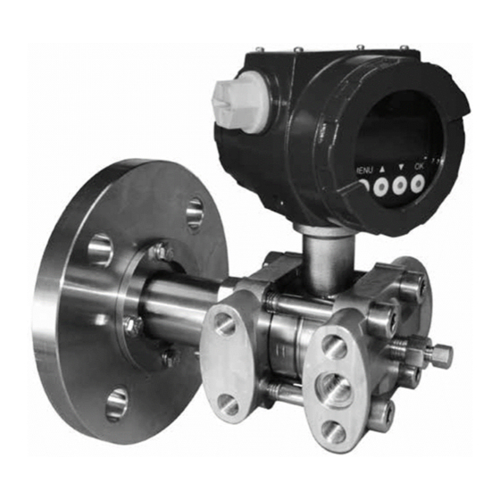
Level Transmitter
Series LD357BL
S U S T A I N A B I L I T Y
1. Safety information
2. Introduction
3. Description
4. Operations
5. Configuration
6. Maintenance and
Troubleshooting
7. Marking
8. Data Sheet
EMM Issue 4 - 2018
© Copyright 2016
Advertisement
Table of Contents

Related Manuals for Spirax Sarco LD357BL Series

Summary of Contents for Spirax Sarco LD357BL Series
- Page 1 3.887.5275.240 EMM Issue 4 - 2018 Level Transmitter Series LD357BL Installation and Maintenance Instructions 1. Safety information 2. Introduction 3. Description 4. Operations 5. Configuration 6. Maintenance and Troubleshooting 7. Marking 8. Data Sheet © Copyright 2016 E X P E R T I S E S O L U T I O N S S U S T A I N A B I L I T Y...
-
Page 2: Safety Information
1. Safety information Safe operation of these products can only be guaranteed if they are properly installed, commissioned, used and maintained by qualified personnel (see Section 1.11 on this document) in compliance with the operating instructions. General installation and safety instructions for pipeline and plant construction, as well as the proper use of tools and safety equipment must also be complied with. Intended use The trasmitters object of the present instructions comply with the directive ATEX 2014/34/UE and are characterized by the following motodhds of protection: II 1G Ex ia IIC T6 Ga They are suitable for installation in Zone 0, Zone 1, Zone 2. For connections and installation refer to this manual. Access Ensure safe access and if necessary a safe working platform (suitably guarded) before attempting to work on the product. Arrange suitable lifting gear if required. -
Page 3: Protective Clothing
1.10 Protective clothing Consider whether you and/or others in the vicinity require any protective clothing to protect against the hazards of, for example, chemicals, high /low temperature, radiation, noise, falling objects, and dangers to eyes and face. 1.11 Permits to work All work must be carried out or be supervised by a suitably competent person. Installation and operating personnel should be trained in the correct use of the product according to the Installation and Maintenance Instructions. Where a formal ‘permit to work’ system is in force it must be complied with. Where there is no such system, it is recommended that a responsible person should know what work is going on and, where necessary, arrange to have an assistant whose primary responsibility is safety. Post ‘warning notices’ if necessary. 1.12 Electrical work Before starting work study the wiring diagram and wiring instructions and note any special requirements. Consider particulary: mains supply voltage and phase, local mains isolation, fuse requirements, earthing, special cables, cable entries / cable glands, electrical screening. -
Page 4: Product Overview
2. Introduction Product Overview The Spirax Sarco LD Series electronic transmitters are devices that use a sensor to measure pressure, level and temperature, and transmit a current signal (4 ÷ 20mA) proportional to the measured variable. The LD Series consists of the following models: TT352 Electronic temperature transmitter LD256 Electronic pressure transmitter LD357B Electronic differential pressure transmitter LD357BL Electronic level transmitter Attention! This manual does not contain information concerning all type of Transmitter or all different installation and/or working and mounting solutions. For more information or for particular problems not considered in this manual, please address to our technical office. The warranty period is the one contemplated in our general servicing conditions. This warranty is neither increased nor restricted by the contents of this manual. This Transmitter has to be installed and used only by qualified persons who have first checked the correctness of supply voltage so that both in standard working conditions and in presence of damages of the plant or of any part of it, no dangerous voltage can reach the Transmitter. -
Page 5: Definitions And Symbols
2.3 Definitions and Symbols In this manual are used the following symbols and labels: Equipment for use in potentially explosive atmospheres Equipment Group II Category 1G, suitable for potentially explosive Zone 0 area II 1G (gases, vapours or mists) and with redundancy for zone 1 and 2 Ex ia Equipment protection by intrinsic safety, level of protection "ia" Group IIC apparatus, fit for substances of group IIC, IIB and IIA Temperature Class of the transmitter (maximum surface temperature) only when used in the ambient temperature range -40°C ÷ 40°C only when used in the ambient temperature range -40°C ÷ 55°C only when used in the ambient temperature range -40°C ÷ 80°C Equipment with equipment protection level (EPL) "Ga" Warning! Warning label, used to warn about hazardous materials, locations, or objects, including electric currents, poisons, and other things. Prohibition! Prohibition label, used to indicate something is not permitted. Mandatory! Mandatory label, used to set obligation tasks to be performed by the user. Information! Information label, used to set general information for the user or warn about ha- zards for the equipment. 3.887.5275.240... - Page 6 3. Description The LD357BL series SMART differential pressure transmitters are microprocessor based instruments that combine the analog signal advantages (4-20mA) together with the flexibility of digital communication using HART protocol. They can be remotely configured by a universal ® hand held terminal (HHT) or by a PC with a dedicated interface. Moreover, it is possible to locally configure the instruments (zero and span) by means of push buttons and to display the data on the wide LCD display. The transmitter series LD357BL, measure differential pressure with spans from 1.2 to 20000 mbar with a static pressure up to 200 bar. The pressure measuring element is a piezoresitive sensor. It is possible to choose a variety of sensors to satisfy all process conditions. The Spirax Sarco measuring cell contains the sensor and transmits the pressure to the electronics.
-
Page 7: Transmitter Identification
4. Installation 4.1 Transmitter Identification Transmitter data can be found on the nameplate fixed on the top of transmitter enclosure (see Marking). The Serial Number must be quoted at the occurrence of a specific request to the manufacturer. General mounting requirements Prior installation shall be observed following considerations: - Check whether Transmitter’s operating conditions are within the limits as reported in the nameplate, technical specifications sheets and/or label. - Make sure that the operating conditions are compatible with the specification given to the manufacturer. Mandatory! - For measurement in the presence of particularly hot liquids (e.g. steam) make sure that the Transmitter is supplied with a suitable finned arm or siphon. - For viscous liquids or those containing solid particles in suspension make sure that the connection to the process is a suitable one in order to avoid clogs. Warning! Direct sunlight may cause serious damages to the instrument. Never install standard Transmitter under the sun or in any other location which could cause direct overheating through radiation. -
Page 8: Mechanical Installation
Mechanical Installation The Transmitter should be located, if possible, at some easily accessible, well lighted place on the vessel, in order to allow putting in operations and maintenance work. Location should also be such that ambient temperature at the Transmitter enclosure be not excessive (see MARKING). Information! - Plant overpressure / over-temperature: observe rating plate. - Installation on seismic areas: inform technical department. - In case of unstable fluids: inform technical department. - In case of damages: inform technical department. - Inspection frequency: consideration should be given to applicable national legislation. Warning! - The process connection must be realized in such a way that guarantees the hold at the maximum working pressure and temperature. - Do not overcome the maximum pressure and temperatures indicated in the technical data sheet of the selected model. - Page 9 - side (ATM) + side Fig. 3 - Level measurement in open vessels Tank pressure - side + side Fig. 4 - Level measurements in closed vessels 3.887.5275.240...
- Page 10 Information! - Referring to Fig. 4: the descending pipes can be filled with condensate vapors of the process fluid or with suitable inert liquid to prevent direct contact with the transmitter diaphragm. Electronic head orientation In order to rotate the electronic head in the desired position you must follow these passages (Fig. 5): • unscrew the 2 stop dowels (A) with key CH.2; • by hand gently rotate the enclosure (B) in the desired position; • once the desired position is reached fix the stop dowels (A) again with the same key. Fig. 5 - Rotating the transmitter head Information! It is not necessary to turn off the supply. 3.887.5275.240...
-
Page 11: Electrical Connection
Electrical connection Under the rear cap is placed the terminal block reporting the electric polarity (Fig. 6). Insert the power supply cable into the enclosure through one of the two threaded openings. Transmitter is protected from accidental inversion of polarity. For a better use is recommended a twisted pair cable (22 AWG min). Avoid placing Transmitter near devices powered in AC or Switching. Connect ground-tap of the Transmitter to the local common earth (PE) as indicated in paragraph Earthing. Warning! The threaded opening that is not used must be sealed using a suitable cap. The caps included in the delivery are only for protection during transport. Loop 4-20 mA For remote indicator (OPTIONAL) Loop 4-20 mA Earthing Fig. 6 - Electrical connection of the power cable to the terminal block Information! Impedance of the cables defines the possible maximum length for digital communication. It's recommended using cable with a low impedance. The maximum... -
Page 12: Operating Area
Mandatory! In order to obtain a 4÷20 mA + Hart output a minimum load of 250 Ohm is required. ® Operating area 12.5 17.4 25.2 Fig. 7 - Operating area for Ex ia protection The electronic transmitters totally comply with the HART protocol specification Revision 6.0, so they ® include remote process variable interrogation, parameter setting and diagnostics. The device is a 4÷20mA 2-wire transmitter, with FSK communication. It is possible to read via HART the following variables: ® PV: transmitter main measure; SV: % of the span; TV: analog output; ... - Page 13 Information! Ref. to Fig. 8: only one transmitter could be connected to each barrier. Ref. to Fig. 9: up to three transmitters can be connected to each barrier with a maximum of 5 Ex ia barriers. ATEX NORMAL ZONE ZONE Fig. 8 - 4÷20 mA + Hart modem connection with Ex ia barrier ® ATEX NORMAL ZONE ZONE Fig. 9 - Only HART Multidrop connection ® 3.887.5275.240...
- Page 14 Fig. 10 - DCS connection Mandatory! Transmitter response time is <256ms. DCS Polling time must be set approximately at 800ms in order to avoid updating problems both in analog and digital measurement. On request the transmitter can be supplied in order to support a Polling time of 500ms but with a minimal consumption of 5 mA. Intrinsic Safety Protection In case of use in areas with danger of explosion, it must be verified that the identified type of transmitter fits for the classification of the zone and for the presence of flammable substances in the plant (see MARKING).
- Page 15 The evaluation of the system formed by the associated apparatus, the transmitter and the connecting cables must be performed by experienced personnel and must be in accordance with the requirements of EN 60079-25 concerning intrinsically safe systems. For proper installation must take into account the safety instructions of the barrier used. Warning! The choice of the associated apparatus has to be made based on the maximum input parameters of the transmitter Maximum input parameters of the equipment (relative to the intrinsically safety): Tamb Tamb Parameter ≤ 60°C ≤ 80°C Output signal 4÷20 mA 4÷20 mA Input voltage 30 V 25.2 V Input current 100 mA 100 mA (li)
- Page 16 Earthing Warning! The earth connection is required to prevent damage to people and malfunction of the instrument. - Case 1: Installing the instrument in a plant devoid of earthing systems In the case where the plant devoid of earthing, it is necessary to connect the earth wire to the terminal block through the cable that carries the signal and the power supply (Fig. 6). - Case 2: Installing the instrument in a plant provided with earthing systems Make sure the earthing (GND) of the system has the least resistance possible. You can add an additional earth wire with section not less than 4 mm to ensure such connection.
- Page 17 Fig. 12 - Earthing in the housing Warning! The hose must not be considered as a protection against electric shock for the protection of security, but as protection against electromagnetic interference of the instrument. Therefore, in the case of long distance cable (L> 20 m), both ends of the braid must be connected to the chassis or to the connectors. In the case of cables L <20 meters, will be sufficient to connect the braid only from the side “Power Supply”. Fig 13 - Earthing of the shield for cables longer than 20 meters 3.887.5275.240...
- Page 18 5. Operations Operations Each transmitter is calibrated in factory and has on the nameplate the configuration data. If not differently stated in the purchase order the transmitter is configured as follow: Upper Range Value (Higher pressure value): refer to the data sheet of unit Lower Range Value (Lower pressure value): refer to the data sheet of unit Damping 0 sec. 5.2 Configuration The transmitter shows the status and the measure on the dot matrix LCD (Fig. 14). The span is from -99999 to 999999. The input signal to the transmitter can be related to the output signal in the following ways: Direct mode = 4÷20mA output Reverse mode = 20÷4mA output The direct mode is obtained by setting the lower range point with the lowest value of the range (e.g. 0 mmH20) and by setting the upper range point with the highest value (e.g. 500 mmH20). The reverse mode is obtained by setting the lower range point with the highest value of the range (e.g. 500 mmH20) and by setting the upper range point with the lowest value (e.g. 0 mmH20). It is possible to display the temperature value of the control board by pressing the following button during transmitter operation: = electronic board temperature. The unit of measure (°C/°K/°F) is defined in the entry TEMP UNIT in the keyboard menu (Fig. 14). Displayed value Displayed value Bar graph / % Span Bar graph / % Span Measuring unit Measuring unit...
-
Page 19: Keyboard Configuration
5.3 Keyboard Configuration The electronic transmitters have some configuration functions available via keyboard and LCD display, provided with the transmitters themselves. Press the [MENU] button to enter the password entering dialog (the default password is 0000). Confirm by [OK] to enter the configuration menu. The display will allow to choose from the different functions described in the table below. Use the and buttons to show the sequence of the available functions and press [OK] to confirm the selected function. When the display is in numerical entering mode, the cursor will blink. To move the cursor press the ; button; to raise the value of the digit press the button. Press the [OK] button to confirm; use instead the [MENU] button to cancel the modifications and to go back to the standard display. Display Function Choice span... - Page 20 Display Function Choice span name NONE = no action 21mA Fault ALARM Fault condition analog output configuration TYPE selection. 3.85mA LAST = last read value Damping DAMP Insert the signal averaging time 0÷60s setting VALUE constant. At the button pushing the transmitter performs the zero elevation, in Automatic OFFSET manner to put to zero the actual zero elevation measure.
- Page 21 Display Function Choice span name Allows to insert a new password Password PASSWORD for the transmitter. To be used 0000÷9999 setting with care. Expert ZERO ELEV. command: (disabled in 6 digits, including "–" sign and Manual zero elevation insertion. Manual zero volumetric decimal point elevation flow meters mode) Expert Reduce the upper range limit...
-
Page 22: Maintenance And Troubleshooting
6. Maintenance and Troubleshooting Although transmitters LD series do not require a maintenance on periodical basis, it is good practice to regularly check the general transmitter status, the possible presence of rust or damage on the case or on the measuring diaphragm and the presence of clogging in the process connection. Prohibition! Repair, maintenance and/or overhaul of the equipment shall only be conducted by the manufacturer himself, or by a repairer he has qualified or authorized. Is forbidden during the maintenance operation to use the tool as a handle or step. Please refer to the following pages scheme for troubleshooting. In any case contact our technical department Spirax Sarco for help. Condition Potential source Solution Supply Check the supply voltage to be 12.5Vdc<Vsupply<30Vdc. The transmitter Polarity Check the transmitter connection polarity. doesn’t turn on Electrical load Check that the load is less than the maximum allowed. Accurately verify the compatibility between the process Process and the connection type. -
Page 23: Display Error Codes
Display error codes Type of error Description OVER RANGE: this message is shown if PV is greater than URV by 20% of the span. UNDER RANGE: this message is shown if PV is lower than LRV by 20% of the span. LCD OV: this message is shown if PV < -99999 or PV >99999. In this case LCD OV could depends by damage of sensor or display. EE CHK ERR This message depends by an error configuration of the EEPROM memory . This message is shown if there are PV calculus error in primary ADC input. EE ADC ERR If it persist contact Spirax Sarco for help. This message is shown if there are on external temperature signal calculus T EX AD ER error in secondary ADC input. If it persist contact Spirax Sarco for help. This message is shown if there are on internal temperature signal calculus T IN AD ER error in secondary ADC input. If it persist contact Spirax Sarco for help. Spare Parts Together with the request of spare parts it is required to indicate Serial Number of the Transmitter to control that the correct components will be delivered. Item Product Code Description... - Page 24 7. Marking On the transmitter enclosure is fixed an identification plate with inscriptions showing the characteristic data of the instrument. Refer to Fig. 15, the Transmitter is provided with the following information: 1. Name and address of the manufacturer 2. CE marking followed by the identification number of the notified body involved in the production phase 3. Designation of series or type 4. Serial number (with the Year of construction) 5. ATEX marking for equipment-group II, followed by the specific marking of explosion protection (see Definitions And Symbols) 6. PED essential allowable limits: allowable Fluids, Maximum working pressure (PS), Nominal size (DN), etc. Fig. 15 - Marking plate 3.887.5275.240...
-
Page 25: Functional Data
8. Data sheet 7. Marcatura Functional Data With reference to the following, please note these definitions: Nominal range: (referred to the sensor mounted in the instrument) the measured pressure range for which the sensor has been designed. Defined as a minimum and maximum value. Nominal span: the interval between the minimum and maximum values of the sensor nominal range. The span is a single number. Measuring range: the minimum and maximum range values for which the transmitter is to be calibrated. Measuring span: the interval between minimum and maximum values of the measuring range. Input scale initial value or zero input: minimum pressure value within in the measuring range. Input full scale value: maximum pressure value within in the measuring range. Transmitter Parameters The parameters that are available for display and setting are: Measuring span: possibility to change from 3.33% to 200% of the nominal span. -
Page 26: Physical Specifications
Influence of Operating Conditions Thermal drift: it is referred to -10 ÷ +80°C range. Zero: ± 0.1%/10°C. Span: ± 0.1%/10°C at nominal range. Static pressure effect Nominal range 18-50 mbar: Zero: ± 0.4% / 10bar. Span: 0.4% / 10bar. Nominal range 350-2500 mbar: Zero: ± 0.1% / 10bar. Span: 0.1% / 10bar. Nominal range 5000-10000 mbar: Zero: ± 0.2% / 10bar. Span: 0.2% / 10bar. Over range effect Nominal range 18-50 mbar: Zero: on either side ± 1% at 50bar. Nominal range 350-2500mbar: Zero: on either side ± 0.1% at 100bar. Nominal range 5000-10000mbar: Zero: on either side ± 1% at 100bar. Power supply effect: Negligible between 12.5 and 30 Vdc. Physical Specifications Housing: die cast aluminum alloy EN AB-44100 finished with epoxy resin (RAL 5010), gasket as specified. It is dust and sand tight and protected against sea wave effects as defined by IEC IP66. -
Page 27: Main Dimensions
Main Dimensions Fig. 16 - Main dimension (mm) 3.887.5275.240... - Page 28 SERVICE For technical support, please contact our local Sales Engineer or our Head Office directly: Spirax Sarco S.r.l. - Technical Assistance Via per Cinisello, 18 - 20834 Nova Milanese (MB) - Italy Tel.: (+39) 0362 4917 257 - (+39) 0362 4917 211 - Fax: (+39) 0362 4917 315 E-mail: support@it.spiraxsarco.com LOSS OF GUARANTEE Total or partial disregard of above instructions involves loss of any rights to guarantee. Spirax-Sarco S.r.l. - Via per Cinisello, 18 - 20834 Nova Milanese (MB) - Tel.: 0362 49 17.1 - Fax: 0362 49 17 307 3.887.5275.240...
Need help?
Do you have a question about the LD357BL Series and is the answer not in the manual?
Questions and answers