Sign In
Upload
Download
Table of Contents
Contents
Add to my manuals
Delete from my manuals
Share
URL of this page:
HTML Link:
Bookmark this page
Add
Manual will be automatically added to "My Manuals"
Print this page
×
Bookmark added
×
Added to my manuals
Manuals
Brands
Fiso Manuals
Measuring Instruments
EasyGrid
User manual
Fiso EasyGrid User Manual
Hide thumbs
Also See for EasyGrid
:
User manual
(31 pages)
1
2
Table Of Contents
3
4
5
6
7
8
9
10
11
12
13
14
15
16
17
18
19
20
21
22
23
24
25
26
27
28
29
30
31
32
33
34
35
36
37
38
39
40
41
42
43
44
45
46
47
48
49
50
51
52
53
54
55
56
57
58
59
60
61
62
63
64
65
66
67
68
69
70
page
of
70
Go
/
70
Contents
Table of Contents
Bookmarks
Table of Contents
Table of Contents
2 Product Certification
CE Information
Independent Laboratory Testing
3 Safety Information
Safety Conventions
Unpacking and Inspection
4 First Steps
Introducing the Nortech Easygrid
Quick Start
Powering the Easygrid
Connecting Temperature Sensors
Reading Temperature Measurements
5 Hardware Configuration
Dimensions
Front Panel Overview
Bottom Panel Overview
Maintenance Panel Overview
TFT Display
Action Buttons or State Icons
Communication and System Status LED
USB Configuration Port
Power Input
Power Switch
Analog Output
RS-485/RS-422 Ports
Programmable Alarm/Relay Terminal Block
System Relay (Fail Safe)
Protective Conductor Terminal
Optical Connector
Ethernet Port (Optional)
6 Firmware Settings
Channel Settings
Alarm Settings
Statistic Settings
Analog Output Settings
Information Settings
Log Settings
Display Settings
Communication Settings
7 Monitoring Screens
Temperature Values & Alarm State
Alarm
Statistics
Analog
Information
Diagnostic
8 Nortech Client Software
Getting Started
Installing the Program
Main Window
Connecting to the Easygrid
Firmware Update
9 Resetting to Factory Defaults
10 FISO Contact Information
FISO Service Center
Advertisement
Quick Links
Download this manual
EasyGrid User Guide MAN-00084 R 11.0
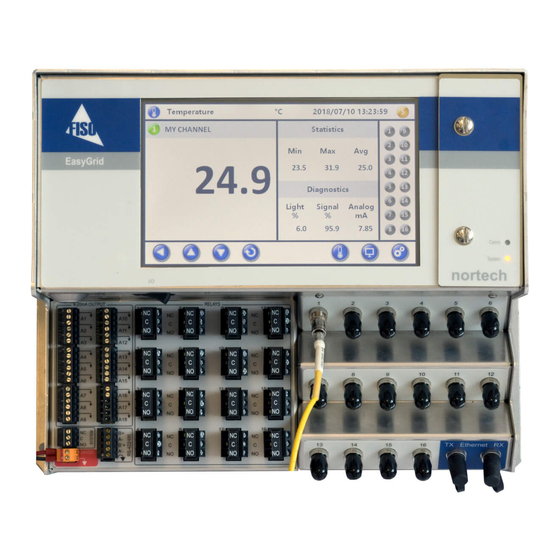
EasyGrid (E-GRID)
User Guide
MAN-00084 R 11.0
i
Table of
Contents
Previous
Page
Next
Page
1
2
3
4
5
Advertisement
Table of Contents
Need help?
Do you have a question about the EasyGrid and is the answer not in the manual?
Ask a question
Questions and answers
Related Manuals for Fiso EasyGrid
Measuring Instruments Fiso EasyGrid Base User Manual
(31 pages)
Measuring Instruments Fiso Nortech EasyGrid LT User Manual
(39 pages)
Measuring Instruments Fiso E-GRID User Manual
(70 pages)
Measuring Instruments Fiso Nortech EasyTest II User Manual
(32 pages)
Measuring Instruments Fiso MAN-00112 R 2.0 User Manual
(34 pages)
This manual is also suitable for:
E-grid
Table of Contents
Print
Rename the bookmark
Delete bookmark?
Delete from my manuals?
Login
Sign In
OR
Sign in with Facebook
Sign in with Google
Upload manual
Upload from disk
Upload from URL


Need help?
Do you have a question about the EasyGrid and is the answer not in the manual?
Questions and answers