Table of Contents
Advertisement
Advertisement
Table of Contents

Related Manuals for Connect Tech XHG101


Summary of Contents for Connect Tech XHG101
- Page 1 Xtreme/GbE - Managed Carrier Ethernet Switch CTIM-00429 Revision 0.11 2021-01-05...
-
Page 2: Table Of Contents
Xtreme/GbE - Managed Carrier Ethernet Switch Users Guide www.connecttech.com TABLE OF CONTENTS Table of Contents ........................2 Preface ............................4 Disclaimer ............................4 Customer Support Overview ......................4 Contact Information ......................... 4 Limited Product Warranty ....................... 5 Copyright Notice ..........................5 Trademark Acknowledgment ......................5 ESD Warning ............................ - Page 3 Xtreme/GbE - Managed Carrier Ethernet Switch Users Guide www.connecttech.com Accessing the Web Management Interface ................... 22 Web Management Interface Overview ..................24 Complete Web Protocol Configuration Reference Guide .............. 24 Factory Default Configuration ....................25 Hardware Usage Examples ......................25 Instructions for Standalone Operation ..................
-
Page 4: Preface
The information contained within this user’s guide, including but not limited to any product specification, is subject to change without notice. Connect Tech assumes no liability for any damages incurred directly or indirectly from any technical or typographical errors or omissions contained herein or for discrepancies between the product and the user’s guide. -
Page 5: Limited Product Warranty
The above warranty is the only warranty authorized by Connect Tech Inc. Under no circumstances will Connect Tech Inc. be liable in any way for any damages, including any lost profits, lost savings or other incidental or consequential damages arising out of the use of, or inability to use, such product. -
Page 6: Esd Warning
ESD Warning Electronic components and circuits are sensitive to ElectroStatic Discharge (ESD). When handling any circuit board assemblies including Connect Tech COM Express carrier assemblies, it is recommended that ESD safety precautions be observed. ESD safe best practices include, but are not limited to: Leaving circuit boards in their antistatic •... - Page 7 Xtreme/GbE - Managed Carrier Ethernet Switch Users Guide www.connecttech.com 0.08 08/09/2017 - Updated Rugged GBE Connector Part Number - Corrected Cable description for CBG127 - Corrected Power Consumption Part labeled 0.09 08/20/2019 Updated 12-Port RJ-45 Image 0.10 12/09/2020 Updated Format 0.11 01/05/2021 Updated Cover Image...
-
Page 8: Introduction
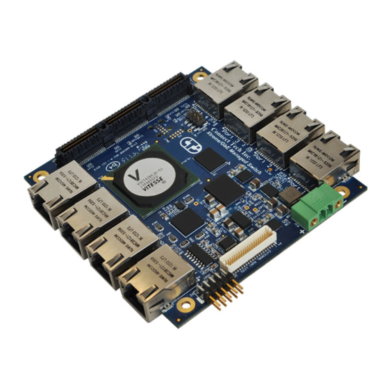
Users Guide www.connecttech.com INTRODUCTION Connect Tech’s Xtreme/GbE Managed Carrier Ethernet Switch provides high density, high port count, Carrier Grade Ethernet switching capabilities in an extremely small embedded form factor. Excellent for any space constrained, mission-critical application needing an embedded high-density/high-port count managed Ethernet Switch. -
Page 9: Part Numbers / Ordering Information
Xtreme/GbE - Managed Carrier Ethernet Switch Users Guide www.connecttech.com Indicator LEDs 2 LEDs per port Power Rail LEDs Status LEDs Standalone Operation Switch can be used as a standalone unit OR it can be paired with an embedded SBC. Input Voltage +9V to 36V Input Range (All Models) +12V only (Models with PCIe/104 Connector) Power Consumption... -
Page 10: Product Overview
XDG022 RJ-45s & Rugged Locking Pin Headers Conduction Cooled Heatplate PCIe/104 XDG023 Rugged Locking Pin Headers Conduction Cooled Heatplate PCIe/104 XHG101 8 or 12 Port Conduction Cooled Heatplate (Standalone Item) PRODUCT OVERVIEW Block Diagram Document: CTIM-00429 Page 10 of 31 Date: 2021-01-05 Revision: 0.11... -
Page 11: Connector Summary & Locations
Xtreme/GbE - Managed Carrier Ethernet Switch Users Guide www.connecttech.com Connector Summary & Locations 8-Port RJ-45 Models Part Numbers: XDG004, XDG005, XDG006, XDG016, XDG017, XDG018 8-Port Rugged Latching Models Part Numbers: XDG007, XDG008, XDG009, XDG016, XDG017, XDG018 Document: CTIM-00429 Page 11 of 31 Date: 2021-01-05 Revision: 0.11... -
Page 12: 12-Port Rj-45 Models
Xtreme/GbE - Managed Carrier Ethernet Switch Users Guide www.connecttech.com 12-Port RJ-45 Models Part Numbers: XDG010, XDG012, XDG022 12-Port Rugged Latching Models Part Numbers: XDG013, XDG023 Document: CTIM-00429 Page 12 of 31 Date: 2021-01-05 Revision: 0.11... -
Page 13: Detailed Feature Description
Xtreme/GbE - Managed Carrier Ethernet Switch Users Guide www.connecttech.com DETAILED FEATURE DESCRIPTION 10/100/1000 Ethernet RJ-45 Connector Function LAN Connector Locations P1-P8 (XDG004/5/6) P3A-J (XDG010) 7498111120 - Manufacturer: Wurth Connector Mating Standard Cat5e (8P8C RJ-45 Plug) Connector Pinout Signal MX1P MX1N Green Only = 1Gbps MX2P Green and Yellow = 100Mbps... -
Page 14: External Led Connectors
Xtreme/GbE - Managed Carrier Ethernet Switch Users Guide www.connecttech.com MX2+ Ethernet Pair 2 Side view looking at connector RJ Shell SHELL Connection RJ Shell SHELL Connection MX3- Ethernet Pair 3 MX3+ Ethernet Pair 3 MX4- Ethernet Pair 4 MX4+ Ethernet Pair 4 External LED Connectors Function External Port LEDs... -
Page 15: Idc Serial Management Connector (Rj-45 Models)
Xtreme/GbE - Managed Carrier Ethernet Switch Users Guide www.connecttech.com Pinout (XDG010) IDC Serial Management Connector (RJ-45 Models) Function Serial Management Connector Top view Locations P2 (8-Port Models) P6 (12-Port Models) TSW-105-08-L-D-RA - Manufacturer: Connector Samtec Mating Any IDC 2x5 0.1” pitch female assembly. Connector Pinout Signal... -
Page 16: Rugged Locking Serial Management Connector (Rugged Models)
Xtreme/GbE - Managed Carrier Ethernet Switch Users Guide www.connecttech.com Rugged Locking Serial Management Connector (Rugged Models) Function Serial Management Connector Top view Locations 98464-G61-10ULF - Manufacturer: FCI Connector Mating 10073599-010LF - Manufacturer: FCI Connector Pinout Signal Side view looking at connector System Jumper Block Function System Jumper Block... - Page 17 Xtreme/GbE - Managed Carrier Ethernet Switch Users Guide www.connecttech.com these pins functionality at this time UART Source JUMPER ON = Select VSC7428 UART connects to PCIe/104 Bus (Only present on XDG006 and XDG009) JUMPER OFF = VSC7428 UART connects to External Management Port (P2)
-
Page 18: Pc/104 Connector
Xtreme/GbE - Managed Carrier Ethernet Switch Users Guide www.connecttech.com VSC7428 UART connects to External Management Port (P2) PC/104 Connector Function PC/104 Connector Locations P9, P10 (8-Port Models) Type PC/104 Stacking Connector Pinout Pinout compliant to PC/104 specification pinout. This connector is only used to * Shown uninstalled source power for the board (+12V), all other pins will be pass-through. -
Page 19: On-Board Indicator Leds (8-Port Models)
Xtreme/GbE - Managed Carrier Ethernet Switch Users Guide www.connecttech.com Standalone Power Requirements Minimum Voltage +9 VDC Maximum Voltage +36 VDC Bus Mode Power Requirements Bus Connector Voltage Rail used PC/104 +12V PCIe/104 +12V External Input Power Connector Details Function Main Input Power +9V to +36V: All Models Locations P16 (8-Port Models) -
Page 20: On-Board Indicator Leds (12-Port Models)
Xtreme/GbE - Managed Carrier Ethernet Switch Users Guide www.connecttech.com has properly powered its internal circuitry On-board indicator LEDs (12-Port Models) Function Details Gigabit Ethernet LED’s Rugged Positive Locking Header GbE LED (Operation similar to RJ-45 Green LED) Gigabit Ethernet LED’s Rugged Positive Locking Header GbE LED (Operation similar to RJ-45 Yellow LED) Xtreme/GbE Main Status... -
Page 21: Cli Management Interface
Xtreme/GbE - Managed Carrier Ethernet Switch Users Guide www.connecttech.com CLI MANAGEMENT INTERFACE CLI Access via External Serial Port To use the CLI management on the XDG you must connect to the RS-232 external management serial port. Only TX, RX and GND connections are needed for operation. You then must open the serial port in a terminal program such as: RealTerm, Putty, HyperTerminal, minicom, etc. -
Page 22: Complete Cli And Protocol Configuration Reference Guide
Xtreme/GbE - Managed Carrier Ethernet Switch Users Guide www.connecttech.com show int * status What ports are linked and at what speed? show ver What software version is on my switch? copy running-config startup-config How do I save my configuration? conf t How do I setup my IP address for vlan1? int vlan 1 ip add xxx.xxx.xxx.xxx 255.255.255.0... - Page 23 Xtreme/GbE - Managed Carrier Ethernet Switch Users Guide www.connecttech.com • configure terminal • interface vlan 1 ip address xxx.xxx.xxx.xxx 255.255.255.0 • • • Now connect Xtreme/GbE to any place on your network. Once the system is up simply go to your specified address of xxx.xxx.xxx.xxx in a web browser of •...
-
Page 24: Web Management Interface Overview
Xtreme/GbE - Managed Carrier Ethernet Switch Users Guide www.connecttech.com Web Management Interface Overview Complete Web Protocol Configuration Reference Guide As mentioned in the CLI section, the complete Protocol Configuration reference guide from Microsemi for the VSC7429 device can be downloaded here. It will have CLI and Web configuration methods listed. The following document: - AN1115Layer2ProtocolConfigurationGuide Will have the below mentioned copyright notice. -
Page 25: Factory Default Configuration
Xtreme/GbE - Managed Carrier Ethernet Switch Users Guide www.connecttech.com FACTORY DEFAULT CONFIGURATION The factory default configuration is a VLAN unaware L2 switch with automatic learning/ageing and auto negotiation enabled on all ports: • System: The system name string is empty. •... -
Page 26: Stacking Multiple Xtreme/Gbe Boards To Achieve Higher Port Densities
Xtreme/GbE - Managed Carrier Ethernet Switch Users Guide www.connecttech.com Stacking Multiple Xtreme/GbE Boards to Achieve Higher Port Densities Due to the stacking nature of the PC/104 and PCIe/104 for factor board, the Xtreme/GbE can easily be stacked with other XDGs to achieve higher switch port densities. Some simple topology examples are listed below to achieve 7 downstream ports with one XDG, 13 downstream ports with two XDG’s and 20 downstream ports with 3 XDG’s. -
Page 27: Thermal Details
Thermal Resistance @ Forced Air Flow: 5°C/W @ 500 LFM Conduction Cooled Heatplate All conduction cooled models of the XDG ship with the XHG101 heatplate. This heatplate has an outer dimensions that are equal to the PC/104 form factor of 3.775” x 3.550”, with a height of 0.435”. -
Page 28: Mechanical Drawings & Models
Xtreme/GbE - Managed Carrier Ethernet Switch Users Guide www.connecttech.com MECHANICAL DRAWINGS & MODELS 3D STEP Models A complete 3D STEP Model file of COM Express Type 6 104e Carrier can be downloaded here: https://www.connecttech.com/ftp/3d_models/XDG-Gen2_3D_MODEL.zip 2D Dimension Drawings 8-Port RJ-45 Models Document: CTIM-00429 Page 28 of 31 Date: 2021-01-05... -
Page 29: 8-Port Rugged Model
Xtreme/GbE - Managed Carrier Ethernet Switch Users Guide www.connecttech.com 8-Port Rugged Model Document: CTIM-00429 Page 29 of 31 Date: 2021-01-05 Revision: 0.11... -
Page 30: 12-Port Rj-45 Model
Xtreme/GbE - Managed Carrier Ethernet Switch Users Guide www.connecttech.com 12-Port RJ-45 Model 12-Port Rugged Model Drawing TBD. Document: CTIM-00429 Page 30 of 31 Date: 2021-01-05 Revision: 0.11... -
Page 31: Cables
Xtreme/GbE - Managed Carrier Ethernet Switch Users Guide www.connecttech.com CABLES The Xtreme/GbE Managed Carrier Ethernet Switch has following cable options available. Drawing No. Part No. Description CTIC-00048 CAG104 2x5 0.1” IDC to DB-9 cable CTIC-00433 CBG117 RJ-45 panel mount to 10-pin MiniTek CTIC-00388 CBG127 DB9 panel mount to 10-pin MiniTek...
Need help?
Do you have a question about the XHG101 and is the answer not in the manual?
Questions and answers