Table of Contents
Advertisement
Quick Links
Advertisement
Table of Contents

Related Manuals for Pulsar MICROFLOW


Summary of Contents for Pulsar MICROFLOW
- Page 1 ICRO NSTRUCTION ANUAL...
- Page 3 Pulsar Process Measurement Limited operates a policy of constant development and improvement and reserves the right to amend technical details as necessary. The MicroFlow shown on the cover of this manual is used for illustrative purposes only and may not be representative of the actual MicroFlow supplied.
-
Page 5: Table Of Contents
....................1 About this Manual ............................1 About the MicroFlow ............................2 Benefits ................................3 Functional Description ............................ 4 Limitations of use ............................4 Product Specification............................5 EU Declaration of Conformity ........................6 ..................... 7 Unpacking ................................ 7 Power Supply Requirements ........................... 7 Cable screen and Earth Requirements ...................... - Page 6 ..................58 ......................59...
-
Page 7: About This Manual
Congratulations on your purchase of a Pulsar MicroFlow. This quality system has been developed over many years and represents the latest in high technology flow monitoring. It has been designed to give you years of trouble free performance, and a few minutes spent reading this operating manual will ensure that your installation is as simple as possible. -
Page 8: About The Microflow
PC software is available to allow setup and run diagnostics using MicroFlow PC via a RS 485 connection. The MicroFlow is compatible for use with Pulsar’s, FlowCERT, Velocity Interface and Ultimate controllers to obtain velocity readings. The MicroFlow can also be retrofitted to replace existing in- process contacting sensors. -
Page 9: Benefits
Virtually maintenance free; not affected by sedimentation, so there is no need for regular cleaning. • Compatible with Pulsar’s FlowCERT, Velocity Interface and Ultimate controllers, with retrofit capability for in-contact sensors. • Can be installed in addition to existing in process contact measuring devices. -
Page 10: Functional Description
The MicroFlow must be routinely inspected to avoid the build-up of dust layers when installed in to Zone 21 & Zone 22. Electrostatic hazard – The MicroFlow must only be wiped with a damp or antistatic cloth. Only leaded little fuses (0242 series) of 100mA should be used with the Ex mb approved MicroFlow. -
Page 11: Product Specification
Win 7, Win 8, Win 10 10 – 28 V DC Operating Voltage Power Consumption 0.36W Pulsar Process Measurement Limited operates a policy of constant development and improvement and reserve the right to amend technical details as necessary. Page 5... -
Page 12: Eu Declaration Of Conformity
EU Declaration of Conformity Page... -
Page 13: Unpacking
If there is any shortage or obvious shipping damage to the equipment, report it immediately to Pulsar Process Measurement Limited. Power Supply Requirements The MicroFlow can operate from a DC supply of 10 to 28V. In all cases the unit typically consumes 0.36W of power. Cable screen and Earth Requirements A screened 5-core cable should be used (minimum conductor size of 0.5mm²) and... -
Page 14: Location
MicroFlow can be correctly installed. The bracket can be used if the MicroFlow sensor is to be mounted on its own in a specific location or along with a Pulsar dB transducer. Please see ‘Angled Mounting Bracket’ for dimensions of this bracket, please note that the drawing is not to scale. -
Page 15: Angled Mounting Bracket
Angled Mounting Bracket Part number: dBA0008MF 176mm Side view Side view R20mm 22mm 22mm 100mm 12mm 90mm 130mm Top view Page 9... - Page 16 100mm 20mm 20mm 60mm R20mm 14mm 100mm 4 off 12mm 60mm 26mm Rear view Important Information Using a spirit level, ensure that the Mounting Bracket is level before attaching the sensor to the bracket. Page...
-
Page 17: Microflow Sensor
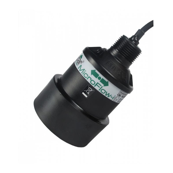
MicroFlow sensor The dimensions of the sensor body are shown below in Fig.1 and Fig.2: 78 mm 1” BSP 73 mm 90 mm BOTTOM Fig.1 Green ‘Dot’ to be positioned on top of sensor. 45° Fig.2 Surface of measurement To obtain the most accurate results, ensure the device is mounted at a 45°... -
Page 18: Mounting Sensor To A Bracket
Fig.3 For correct installation, we recommend that the adapter is threaded on the cable, and carefully screwed onto the MicroFlow before fitting to the bracket. This will reduce the risk of any ’twisting’ in the cable. Ensure that the sensor is tightened and the dot is in the correct position. - Page 19 Fig.4 Central to the movement of flow in channel. Care should be taken not to overtighten the sensor when everything is connected, as seen in Fig.5 below, as this could cause damage to the housing. 305mm 215mm 205mm Fig.5 Page 13...
- Page 20 When the sensor is mounted on the bracket with dB series level transducer, you are able to position the bracket in a way where the MicroFlow is obtaining measurements following the direction of the flow, or facing the direction of flow.
-
Page 21: Terminal Connection Details
Terminal Connection Details Terminal Connections Power The MicroFlow operates from a DC voltage supply of 10-28 volts, and should be installed and connected in accordance with ‘Chapter 2–Power supply requirements’ and the instructions below. When wiring the MicroFlow the cable used is of a multicore design. -
Page 22: Flowcert Wall Mount
FlowCERT unit. For further information on how to operate a FlowCERT unit, please refer to the separate FlowCERT user manual. To set up a MicroFlow sensor with the FlowCERT please refer to Chapter 5 – Setting up your MicroFlow of this manual. The FlowCERT manual is also available for download from the Pulsar website: https://www.pulsar-... -
Page 23: Velocity Interface
Velocity Interface unit, please refer to the Velocity Interface user manual. To set up a MicroFlow sensor with the Velocity Interface please refer to Chapter 5 – Setting up your MicroFlow of this manual. The Velocity Interface... -
Page 24: Ultimate Controller (Fascia)
The Terminal strip is detailed as below. For further information on how to setup an Ultimate Controller unit, please refer to the Ultimate Controller user manual. To set up a MicroFlow sensor with the Ultimate Controller please refer to Chapter 5 – Setting up your MicroFlow of this manual. The Ultimate Controller manual is also available for download from the Pulsar website: https://www.pulsar-... - Page 25 The Green cable (cable screen) should be connected to Earth such as terminal 6 (0V). Important Information If you require help in connecting the MicroFlow to any of the Pulsar controllers mentioned in this manual, then please contact your local Pulsar Distributor for assistance.
-
Page 26: Ultimate Controller (Wall Mount)
The Terminal strip is detailed as below. For further information on how to setup an Ultimate Controller unit, please refer to the Ultimate Controller user manual. To set up a MicroFlow sensor with the Ultimate Controller please refer to Chapter 5 – Setting up your MicroFlow of this manual. The Ultimate Controller manual is also available for download from the Pulsar website: https://www.pulsar-... - Page 27 The Green cable (cable screen) should be connected to Earth such as terminal 6 (0V). Important Information If you require help in connecting the MicroFlow to any of the Pulsar controllers mentioned in this manual, then please contact your local Pulsar Distributor for assistance.
-
Page 28: Locating The Microflow
For optimum accuracy install the MicroFlow where the flow is not turbulent. An ideal location for the sensor is in the centre of a long straight channel. Vertical drops, baffles, curves or junctions can cause the velocity profile to be distorted. -
Page 29: Hazardous Area Installation
Hazardous Area Installation Not all MicroFlow models are ATEX certified, check label for approval details. The ‘X’ in the certifications number indicates that certain special conditions apply. This version must be supplied from apparatus that provides protection from prospective short circuits up to 1500A. The fuse is fitted in the safe area end of the cable. - Page 30 In the instance where there are vertical drops, baffles, curves or junctions. The sensor should then be positioned on a straight part of the channel, at a minimum distance that is at least five times the width of the channel before a bend, in order to obtain optimal velocity readings.
- Page 31 Diagram 3 Distance Distance Diagram 4 Distance Distance Page 25...
- Page 32 45° Surface of measurement • When using one of the Pulsar Angled Mounting Brackets, secure the bracket using the correct size screws/bolts/U-bolts (12mm diameter thread). • Tighten the sensor into the bend, and then screw the thread adapter onto the bracket using the nut supplied.
-
Page 33: Preparation For Operation
✓ All wiring is correct to a Pulsar controller. ✓ The power supply is correctly installed. General Maintenance There are no user serviceable parts inside MicroFlow. If you experience any problems with the unit, then please contact Pulsar Process Measurement for advice. -
Page 34: Sensor Maintenance
• If using a Pulsar angled bracket, the sensor head is mounted onto the end of the bend via its process fitting, this should be carefully unscrewed in an anticlockwise direction. Ensure that the sensor is not dropped or knocked as this can cause damage to the unit. - Page 35 The correct PPE should be worn on site when performing maintenance on the system, if in doubt please contact your site Health and Safety Officer for further advice. Important Information Care should be taken when removing and cleaning so as to not damage the device.
- Page 36 This page is left blank intentionally Page...
-
Page 37: Measuring Streamflow / Open Channel Flow
In order to set up and obtain readings from your application using the MicroFlow, it is advised to do this using a Pulsar controller. Measuring streamflow / open channel flow. The calculation of flow using Area x Velocity is only possible when the MicroFlow sensor is used as part of an integrated system with either FlowCERT or Ultimate Controllers. -
Page 38: Microflow Protocol
Once the sensor is connected to the controller and power is restored to the device, after a short period of time, the MicroFlow will automatically detect and adjust its protocol and Baud rate to match that of the appropriate Pulsar controller. -
Page 39: Flowcert Setup
This chapter explains the quickest way in which to get your MicroFlow sensor working with the Pulsar controllers that the sensor operates with. FlowCERT setup Install and connect your FlowCERT controller as outlined in the FlowCERT user manual. Install and connect your MicroFlow sensor to the FlowCERT as described in Chapter 2 - Installation - FlowCERT of this manual. -
Page 40: Velocity Interface Setup
Install and connect your Velocity Interface controller as outlined in the Velocity Interface user manual. Install and connect your MicroFlow sensor to the Velocity Interface as shown in Chapter 2 - Installation – Velocity Interface of this manual. Power up the unit and enter program mode by keying in ‘1997’ and pressing Enter to begin setting up the unit for measurement. -
Page 41: Ultimate Controller Fascia And Wall Mount Setup
Select ‘Velocity’ where you will now be able to select the MicroFlow as a velocity measurement point. 10. Select ‘Single’ when only using one sensor to obtain velocity measurements. - Page 42 13. Return to the ‘Main menu’ and select ‘Sensors > MicroFlow’ and enter the maximum velocity in m/s, and adjust any other settings that are required. 14. Touching the MicroFlow picture will allow you to access the sensors trace screen. Here you can see the velocity (m/s), signal strength and confidence of the current reading obtained.
- Page 43 29. Once velocity is detected then this information can be viewed in the auxiliary display. Important Information For further information on how to set up the individual controllers, please refer to that controller’s instruction manual. All of Pulsar’s product manuals are available from the Pulsar website: https://www.pulsar-pm.com/support/downloads/manuals.aspx. Page 37...
- Page 44 This page is left blank intentionally Page...
-
Page 45: Software Installation
OS. These drivers can be installed from your installation disc. Run the MicroFlow PC Setup.exe from the CD, or from the downloaded file from our website to install the MicroFlow PC software correctly, which will automatically install the necessary drivers for your RS485 connector. -
Page 46: Using Microflow Pc
Ensure that power to the controller/sensor is switched ‘OFF’ before removing cables and any connection is made. With the two MicroFlow RS485 cables removed, connect the Red wire with the Red crocodile clip on the connector, to the Orange (RS485+) wire of the MicroFlow. -
Page 47: Flow Tab
Flow Tab The above picture is the default screen of MicroFlow PC, which is the Flow tab. The dial on the left displays the linear flow velocity (up to 6m/s), which is in metres per second. While the numerical display on the right shows the velocity flow rate in different volume and time units. - Page 48 When activated, this icon border will light up yellow and ‘live’ traces can be observed on the ‘Trace’ tab. Click again to deactivate. Save Data to File: Click to record data from the MicroFlow device. When activated, this icon will light up yellow, clicking again will deactivate the feature.
- Page 49 • A prompt will appear for choosing the data files to play. • Select the data files to replay, ensure that on MicroFlow PC recorded data files are selected. • To replay more than one file, select multiple files by holding down the ‘CTRL’...
-
Page 50: Setup Menu
*Switch Device into Bootloader Resets the MicroFlow into Bootloader mode. The Bootloader PC program must be used to connect to the sensor in this mode. The MicroFlow will resume normal operation if no connection is established after approximately 30 seconds. -
Page 51: Tools Menu
Strength and Stability. This information from the MicroFlow could then be placed into a chart/graph format. Chart Data file This opens up the directory folder on your computer where MicroFlow data is currently stored. Info menu Selecting this will allow you to view the following information: MicroFlow PC This displays information showing the version of software currently being used. -
Page 52: Flow Record Tab
When the save data to file function is being used, flow information and traces will be written to file, at the fixed interval selected via ‘Setup > Recording Interval’. See ‘Recording Interval’ in the ‘Using MicroFlow PC’ section of this manual. Page... -
Page 53: Trace Tab
Trace Tab This displays the diagnostic traces from the sensor when the trace button is activated or when replaying a saved file. The vertical axis is related to the signal strength, while the horizontal axis is related to the detected flow. When a signal is received, the ‘green square indicator’... -
Page 54: Parameter Tab
Parameter Tab This tab enables the user to change parameter settings in the MicroFlow sensor. It is important to note the following to ensure that the sensor is correctly programmed. Upon every connection to the sensor, MicroFlow PC will synchronise the values on the Parameter tab to that currently stored on the sensor, including the Modbus ID of the sensor. - Page 55 Setting terminal on the parameters tab, as shown below: All parameters can be queried by entering the parameter address in the Parameter field and then clicking on the Query button. The MicroFlow will then reply with the current value of that parameter.
- Page 56 This page is left blank intentionally Page...
-
Page 57: Parameter Access
Parameter Access All of the MicroFlow sensor parameters have factory default values which the user receives upon first use, or when the sensor is reset. The parameters consist of two main types: Output parameters and Configuration parameters. Output parameters are read only and cannot be set by the user. Examples are the stability and signal strength. -
Page 58: Configuration Parameters
This is a ‘read only’ parameter and gives you the current stability in a percentage, from 1 to 100. Configuration parameters RS485 Communication and Modbus Use these parameters to setup the MicroFlow device to the appropriate Pulsar controller. Parameter Name... - Page 59 100, for 100%. 50% 1 – 500 Cal Factor would half and 200% would double. This sets the damping applied to the MicroFlow sensor. A Damping 0 - 28 higher number represents more damping. This is the number of...
- Page 60 Changing this to ‘Fast’ will automatically calibrate parameters in the MicroFlow sensor to track measurements 0 = Slow faster. This is recommended Response Slow for Pumped flow. ‘Slow’ is 1 = Fast recommended when there is natural flow, as measurements will be tracked at a slower pace.
-
Page 61: Saving & Loading Parameters
Once the parameters have been loaded onto the sensor, it will automatically re-connect to the MicroFlow PC software, where you are able to see the new parameter values. Page 55... -
Page 62: Firmware Upgrade
Click ‘Erase-Program-Verify’ and await for the process to finish. When the ‘Verification Successful’ message is displayed, click ‘Run firmware’ and the Bootloader Interface will close down. Select the ‘connect’ button on the software, and the sensor will reconnect to MicroFlow PC with the new firmware installed. Page... - Page 63 Fig.9 Important Information If the sensor does not connect to the device within 40 seconds, it will resume its normal operation with its current firmware. Do not switch off supply to the unit or close down the software during the firmware upgrade. Page 57...
- Page 64 Symptom What to Do Check power supply. Check wiring to FlowCERT/Velocity the MicroFlow sensor. If sensor has Interface/Ultimate shows “Lost been connected to a new unit, then it comms” may require power cycling to sync with the controllers Baud rate.
- Page 65 Incorrect disposal can cause adverse effects to the environment. Dispose of the device components and packaging material in accordance with regional environmental regulations including regulations for electrical \ electronic products. Transducers Remove power, disconnect the Transducer, cut off the electrical cable and dispose of cable and Transducer in accordance with regional environmental regulations for electrical \ electronic products.
Need help?
Do you have a question about the MICROFLOW and is the answer not in the manual?
Questions and answers