
Related Manuals for Feig Electronic OBID i-scan ID ISC.MAT-B

Summary of Contents for Feig Electronic OBID i-scan ID ISC.MAT-B
- Page 1 MONTAGE ® OBID i-scan INSTALLATION ID ISC.MAT-B Manual Antenna Tuner (English) draft / preliminary / final public (B) 2007-06-26 M70101-0e-ID-B.doc...
- Page 2 FEIG ELECTRONIC call explicit attention that devices which are subject of this document are not designed with components and testing methods for a level of reliability suitable for use in or in connection with surgical implants or as critical components in any life support systems whose failure to perform can reasonably be expected to cause significant injury to a human.
-
Page 3: Table Of Contents
Setting the tuning capacitances ................11 Determining the inductance ..................12 Determining Q......................13 Tuning the antenna .....................14 Technical Data ID ISC.MAT-B Appendix: Helpful tools for constructing and testing antennas Recommended equipment and sources ..............19 FEIG ELECTRONIC GmbH Page 3 of 19 M70101-0e-ID-B.doc... - Page 4 Although this device doesn't exceed the valid limits for electromagnetic fields you should keep a minimum distance of 25 cm between the device and your cardiac pacemaker and not stay in an immediate proximity of the device respective the antenna for some time. FEIG ELECTRONIC GmbH Page 4 of 19 M70101-0e-ID-B.doc...
- Page 5 After assembling the antenna conductor, the antennas are tuned using individually selectable capacitors. Then antenna is then permanently tuned for its local conditions. If it is moved to a different position under different local conditions, retuning of the antenna may become necessary. FEIG ELECTRONIC GmbH Page 5 of 19 M70101-0e-ID-B.doc...
- Page 6 • Jumpers with 2 mm spacing (included in the scope of delivery) More detailed specifications for the devices can be found in the section Appendix: Helpful tools for constructing and testing antennas FEIG ELECTRONIC GmbH Page 6 of 19 M70101-0e-ID-B.doc...
-
Page 7: Wiring And Installation
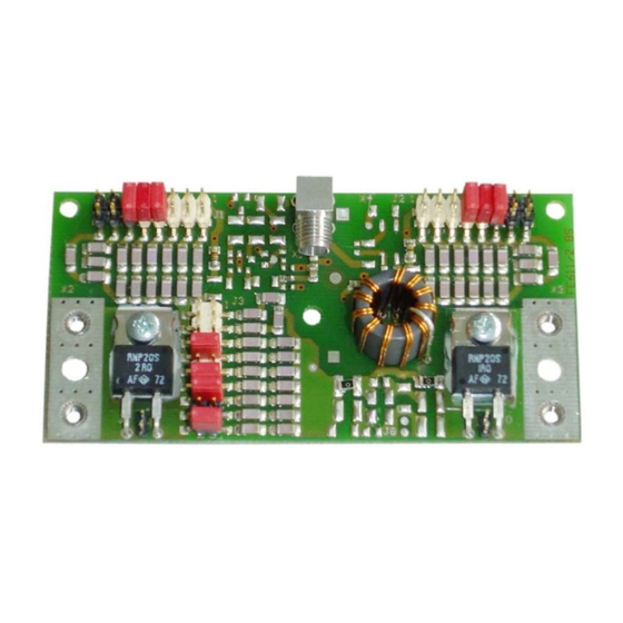
Tuner, see Fig. 1. The antenna loop is attached to X2 and X3 using M3 threaded inserts. Fig. 1: Dimensions and mounting holes The maximum installed height of the circuit board is shown in Fig. 2: Fig. 2: Maximum installed height FEIG ELECTRONIC GmbH Page 7 of 19 M70101-0e-ID-B.doc... -
Page 8: Pin Headers And Hf Connection Sockets
Pin 1 Pin 8 Pin 1 Pin 9 Fig. 3: Headers and HF-sockets The HF cable is connected through the SMA socket X1 as shown in Fig. 4. Fig. 4 HF cable connection FEIG ELECTRONIC GmbH Page 8 of 19 M70101-0e-ID-B.doc... -
Page 9: X2, X3 Connecting The Antenna Conductor
Fig. 6: Antenna connection (coaxial cable RG214) M3x8 Kontur Kupferrohr Kupferrohr (zusammen- gepresst) Leiterplatte Fig. 7: Antenna connection (copper tubing) Note: Ensure that there is good electrical contact between the antenna conductor and the contact surfaces. FEIG ELECTRONIC GmbH Page 9 of 19 M70101-0e-ID-B.doc... -
Page 10: Operating Elements
ID ISCANT800600 1.9µH (Single-Loop: 800mm x 600mm) 6.5 W 3Ω 0Ω ID ISCANT1400700 1.1µH (8-Loop: 1400mm x 700mm) 3Ω The maximum permissible HF power increases if the power is not continuously present. FEIG ELECTRONIC GmbH Page 10 of 19 M70101-0e-ID-B.doc... -
Page 11: Startup
Fig. 8. Jumpers can be used to switch capacitors and C2 into the circuit. Fig. 8: Equivalent schematic for compensation circuit with balloon circuit FEIG ELECTRONIC GmbH Page 11 of 19 M70101-0e-ID-B.doc... -
Page 12: Determining The Inductance
= Side length of the antenna cm = Diameter in cm [here CU tube 1.8 in cm] = Number of turns Inductance of a quadratic antenna Side length [cm] Fig. 9: Inductance of a quadratic antenna FEIG ELECTRONIC GmbH Page 12 of 19 M70101-0e-ID-B.doc... -
Page 13: Determining Q
3 Ω J10 and J9 out Fig. 10 shows insertion of the solder jumpers J9 or J10 on the solder side of the circuit board: Fig. 10:Solder jumpers J9 and J10 in FEIG ELECTRONIC GmbH Page 13 of 19 M70101-0e-ID-B.doc... -
Page 14: Tuning The Antenna
If the particular value cannot be achieved, use the next possible value. J2=C1/2 J1=C1/1 Pin 1 Pin 1 J3=C2 Pin 1 0,5 pF 1Ohm 2 Ohm Fig. 11: Configurable capacitances on the circuit board FEIG ELECTRONIC GmbH Page 14 of 19 M70101-0e-ID-B.doc... - Page 15 (on J3) to recalibrate to the value closest to R=50 Ω and Z = 50 Ω. 5. Use capacitance C 6. If necessary repeat steps 5 and 6 until the working point 50 Ω lies within the specified tolerance (+-3Ω) and no more improvement is possible. FEIG ELECTRONIC GmbH Page 15 of 19 M70101-0e-ID-B.doc...
- Page 16 (see Fig. 12) for the impedance towards lower values. • Changes in the distance from metals, magnetic materials or to the floor detune the antenna after the fact and must be compensated for after installing the antenna. FEIG ELECTRONIC GmbH Page 16 of 19 M70101-0e-ID-B.doc...
- Page 17 The impedance of the antenna should always be set in the intended area of use, since metal or other conducting materials have an effect on the inductance and therefore on the antenna impedance. FEIG ELECTRONIC GmbH Page 17 of 19 M70101-0e-ID-B.doc...
-
Page 18: Technical Data Id Isc.mat-B
10 Hz to 150 Hz : 0.075 mm / 1 g • Shock EN60068-2-27 Acceleration : 30 g Assuming appropriate heat dissipation at power resistors R1 and R2, using for example a heat sink or by the antenna conductor. FEIG ELECTRONIC GmbH Page 18 of 19 M70101-0e-ID-B.doc... -
Page 19: Appendix: Helpful Tools For Constructing And Testing Antennas
• HEINZ BOLLI AG, Rütihofstrasse 1, CH-9052 Niederteufen, Tel. +41(0) 71 335 0720 www.hbad.ch Adapter : UHF-> BNC, BNC-SMA, SMA-SMA, Abschlußwiderstand 50 Ω Supplier: Bürklin OHG, http://www.buerklin.com Conrad.com AG, http://www.conrad.de Farnell Electronic Components GmbH, 82041 Oberhaching, http://www.farnell.com FEIG ELECTRONIC GmbH Page 19 of 19 M70101-0e-ID-B.doc...
Need help?
Do you have a question about the OBID i-scan ID ISC.MAT-B and is the answer not in the manual?
Questions and answers