
Related Manuals for Alecto DVC-266IP


Summary of Contents for Alecto DVC-266IP
- Page 1 Gebruiksaanwijzig Mode D’Emploi Gebrauchsanleutung User manual DVC-266IP Bewakingscamera Caméra de surveillance Überwachungskamera Surveillance camera...
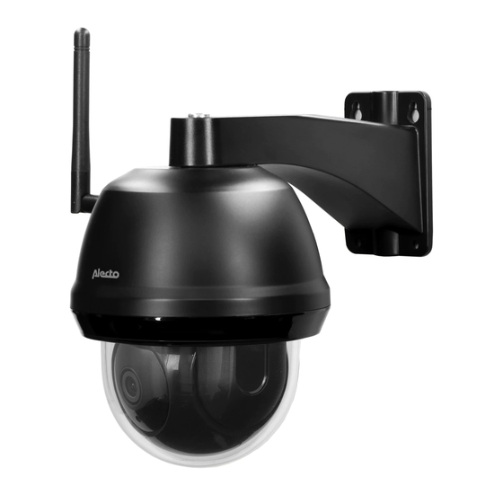
- Page 2 OVERZICHT. 1. antenne 2. antenne aansluiting 3. montage camera 4. reset toets 5. SD kaart sleuf 6. montage voet 7. bescherm afdichting. 8. LAN netwerk aansluiting 9. voeding aanslui- ting 10. UTP koppelstuk 11. lens 12. Beschermkap 13. Inrarood LED Bij montage aan de muur, kunnen de aansluitkabels in de voet worden geplaats.
- Page 3 INSTALLATIE. Monteer de antenne op de micro RESET camera door het voetje op de camera te draaien. Sluit eventueel het LAN netwerk POWER aan, of maak gebruik van WiFi. Sluit de voedingsadapter aan op de voedingsaansluiting (POWER) van de camera. Wacht 2 minuten zodat de camera is opgestart.
-
Page 4: Vue D'ensemble
VUE D’ENSEMBLE. 1. antenne 2. connecteur d’antenne 3. montage de la caméra 4. bouton de réini- tialisation 5. Fente pour carte 6. base de montage 7. sceau de protection 8. Connecteur de réseau LAN 9. connecteur d’alimentation 10. Coupleur UTP 11. -
Page 5: Installation
INSTALLATION. Monter l’antenne sur l’appareil micro RESET photo en faisant tourner le pied de l’appareil. Connecter le réseau LAN si né- POWER cessaire, ou utiliser le WiFi. Branchez l’adaptateur secteur à la prise d’alimentation (POWER) de l’appareil photo. Attendez 2 minutes que l’appareil photo se mette en marche. - Page 6 ÜBERSICHT. 1. antenne 2. Antennenan- schluss 3. Montage der Kamera 4. Reset-Taste 5. SD-Kartenschlitz 6. Montageplatte 7. Schutzdichtung 8. LAN-Netzwer- kanschluss 9. Stromversor- gungsanschluss 10. UTP-Koppler 11. Linse 12. Schutzhülle 13. Infrarot-LED Bei der Wandmontage kön- nen die Anschlusskabel in den Sockel gelegt werden.
- Page 7 INSTALLATION. Befestigen Sie die Antenne an micro RESET der Kamera, indem Sie den Fuß auf der Kamera drehen. Schließen Sie das LAN-Netzwerk an, falls erforderlich, oder ver- POWER wenden Sie WiFi. Schließen Sie das Netzgerät an die Netzsteckdose (POWER) der Kamera an.
- Page 8 OVERVIEW. 1. antenna 2. antenna connec- 3. mounting camera 4. reset button 5. SD card slot 6. mounting base 7. protection seal 8. LAN network connector 9. power supply connector 10. UTP coupler 11. lens 12. Protective cover 13. Infrared LED When mounted on the wall, the connecting cables can be placed in the base.
- Page 9 INSTALLATION. Mount the antenna on the micro RESET camera by rotating the foot on the camera. Connect the LAN network if ne- POWER cessary, or use WiFi. Connect the AC adapter to the power socket (POWER) of the camera. Wait 2 minutes for the camera to starts up.
- Page 10 Maximum Vermogen : < 20 dBm DECLARATION DE CONFORMITE Le soussigné, Hesdo, déclare que l’équipement radioé- lectrique du type Alecto DVC-266IP est conforme à la directive 2014/53/UE. Le texte complet de la déclaration UE de conformité est disponible à l’adresse internet suivante: http://DOC.hesdo.com/DVC-266IP-DOC.pdf...
-
Page 11: Technical Specifications
TECHNICAL SPECIFICATIONS. Image Sensor :1080P High Definition Color CMOS Sensor Display Resolution :1920 x 1080 (2 Mega pixels) Lens :4.1mm Glass Lens Mini. Illumination :0 Lux (With IR Illuminator) Viewing Angle :90 Degree (Horizontal) :45 degree (Vertical) Input Built-in :microphone Output Built-in :speaker Audio Compressioin... - Page 12 Service Help WWW.ALECTO.NL SERVICE@ALECTO.NL Hesdo, Australiëlaan 1 5232 BB, ‘s-Hertogenbosch The Netherlands Service WWW.ALECTO.NL SERVICE@ALECTO.NL Help Hesdo, Australiëlaan 1, 5232 BB, The Netherlands ‘s-Hertogenbosch, V1.2...
Need help?
Do you have a question about the DVC-266IP and is the answer not in the manual?
Questions and answers