Table of Contents
Advertisement
Quick Links
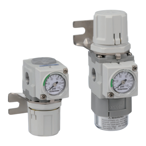
New-generation Filter Regulator
All products are
RoHS compliant
Series
Flexible
Flexible installation
Water removal fu
Water removal fun
Water removal function eliminated for more fl exible installation
Improved operability
Improved knob operability and simple bowl installation and removal
Catalog No. BK-E0010
NPT thread specifi cations
Advertisement
Table of Contents

Related Manuals for Koganei FRZ Series

Summary of Contents for Koganei FRZ Series
- Page 1 Catalog No. BK-E0010 New-generation Filter Regulator Series NPT thread specifi cations Flexible installation Flexible Water removal function eliminated for more fl exible installation Water removal fun Water removal fu Improved operability All products are RoHS compliant Improved knob operability and simple bowl installation and removal...
- Page 2 New-generation Filter Regulator Series Excellent for air lines with water and fl uids already removed. 40 and 50 series 30 series can be used in combinations Specialized standalone application 1.575 1.969 1.378 Regulator Filter regulator Regulator Filter regulator Regulator Filter regulator RZ30 FRZ30 RZ40...
-
Page 3: Compact Design
Improved fl ow rate characteristics enable a smaller confi gura- Water and impurity removal functions have been eliminated for tion. more fl exible installation. Bowl can be mounted on the top or the *Compared to the R600 and RZ50 Koganei Regulator. sides. Filter bowl section 2.992 1.969... - Page 4 Pressure gauge, pressure switch Module adapter Can select various types of pressure gauges and pressure These devices are used to connect devices for the 40 series switches other than the 1.181 in. integrated pressure gauge. and 50 series body sizes. □...
- Page 5 ● Because Koganei products are designed for use under a wide ● After completing wiring work, check to make sure that all variety of conditions, decisions concerning conformance with connections are correct before turning on power.
-
Page 6: Other Precautions
1. Warranty Period sudden operation and may result in injury. Koganei warrants this product for a period of no more ● Do not bring any magnetic media or memory within 3.28 ft of than 180 days from the date of delivery. - Page 7 Handling instructions and Precautions 3. Use the D□ module or a bracket to install all the products. Precautions for the FRZ series 4. The product can be mounted (installed) in any direction. It is Design and selection also possible to install it with the bowl of the filter on top.
- Page 8 1. Use clean air (through 5 μm or smaller filter) for the supply medium. the aluminum die-cast parts of the product, tighten them to the Contact the nearest Koganei sales office or overseas department if torque recommended in our standards.
-
Page 9: Pressure Setting
Contact your nearest Koganei sales office or overseas department. models FRZ4□, FRZ5□, RZ4□, RZ5□) consume air while 5. Contact your nearest Koganei sales office or overseas department if regulating pressure on the OUT port (secondary) side. you are using a circuit that needs highly precise pressure regulation. -
Page 10: Panel Mount
Handling instructions and Precautions Filter regulator Operation and maintenance inspections Regulator ●Locking and releasing the knob 1. The Knobs on the filter regulators and regulators use a push ●Piping work lock mechanism. Connect pipes and fittings to the filter regulator and regulator IN ... - Page 11 ●Removing the knob ● Changing the □1.181 in. integrated pressure gauge and pressure port plate Use the following procedure to remove the knob. Use the following procedure to rotate the □1.181 in. integrated ① Release the knob lock. pressure gauge 180°, and to change the □1.181 in. integrated ...
- Page 12 NOTE of the filter regulator and regulator are coated with grease. bled or reassembled. 3. Contact your nearest Koganei sales office or overseas depart- ment if you are considering re-coating the o-rings and other Regulator and filter regulator knob side parts.
- Page 13 Regulator plug side Plug (tightening torque Residual pressure exhaust valve RZ4□ ・ RZ5□ RZ3□ 1.33 to 1.62 ft lbf) • Mounting (installation) and piping Plug (tightening torque ●Flow mark 2.66 to 3.25 ft lbf) • The following diagram shows the relationship of the direction of O-ring large* flow of the media and the flow mark on the residual pressure exhaust valve.
- Page 14 Handling instructions and Precautions ●Using the lock hole Operation and maintenance inspections 1. The lock hole on the residual pressure exhaust valve is used ●State of air supply and exhaust to secure the air flow in a state of exhaust and to prevent 1.
-
Page 15: Mounting Installation
1. Use the various modules and adapters when combining the rel- 1. The method to install the pressure switch modules is the same evant FRZ series models and the relevant iB-Cyclone* models. for the various modules and adapters. Refer to the "Handling *See the back of the catalog. - Page 16 Handling instructions and Precautions □ 1.181 in. series integrated pressure Operation and maintenance inspections 0 MPa MPa 1.0 gauge ●Detection pressure scale 1. Use a detection pressure scale as a guideline. Mounting (installation) and piping Use a multi meter to confirm the output of the pressure ●Mounting (installation) NOTE switch module.
-
Page 17: Reference Data
Reference data ●About the chemical resistance of polycarbonate The chemicals in the following table degrade polycarbonate. Because of this, they may damage the bowl of the filter regulator or the front cover of the pressure gauge and cause an accident. The products cannot be used in locations where the chemicals in the following table are present in the compressed air, ambient air, or on surfaces. -
Page 18: Filter Regulator
Filter regulator FRZ30-F11 FRZ31-F11 FRZ32-F11 • • FRZ40-F11 FRZ41-F11 • FRZ50-F11 FRZ51-F11 • Symbol ●Standard ●Built-in check mechanism ●Low pressure Specifications Model Standard FRZ30-F11 FRZ40-F11 FRZ50-F11 FRZ31-F11 FRZ41-F11 FRZ51-F11 For low pressure FRZ32-F11 Item Built-in check mechanism Medium Port size M5×0.8mm, NPT1/8, NPT1/4 NPT1/8, NPT1/4, NPT3/8 NPT1/4, NPT3/8, NPT1/2... - Page 19 Order codes ●Parts for maintenance ●Bowl assembly ●Element ●Pressure port plate P-FRZ BA-FRZ□-F11 E-□Z GP-FRZ□-F11 (without pressure gauge connection port) (with pressure gauge connection port) 1 o-ring and Connection port diameter Body size Body size 2 small screws Blank NPT1/4 30 For FRZ3□...
- Page 20 Flow rate characteristics ● Standard and built-in check mechanism FRZ30-F11-M5 FRZ32-F11-M5 FRZ40-F11-01 FRZ50-F11-02 101.5 101.5 101.5 72.5 72.5 72.5 43.5 43.5 43.5 14.5 14.5 14.5 1.75 5.25 ft /min (SCFM) 8.75 17.5 26.25 ft /min (SCFM) 17.5 52.5 ft /min (SCFM) ℓ...
- Page 21 Filter regulator dimensions ●FRZ30-F11 1.969 1.319 1.378 ●FRZ31-F11 1.004 1.378 M28 × 1.5 mm 1.260 ●FRZ32-F11 0.079 For -B OPEN -M5:2-M5 × 0.8mm NPT1/4 -01:2-NPT1/8 -02:2-NPT1/4 Maintenance space at least 1.181 ●Pressure gauge options (2.83) 1.004 For -GS6 For -GN (3.228) 1.378 6...
- Page 22 Filter regulator dimensions ●FRZ40-F11 1.969 1.319 1.378 1.575 1.004 ●FRZ41-F11 M28 × 1.5 mm 1.260 0.079 For -B OPEN -01:2-NPT1/8 -02:2-NPT1/4 NPT1/4 -03:2-NPT3/8 Maintenance space at least 1.181 ●Pressure gauge options (2.83) 1.004 For -GS6 For -GN 1.378 (3.228) 6 0 9...
- Page 23 1.378 1.378 ●FRZ50-F11 1.969 1.083 1.260 ●FRZ51-F11 M28 × 1.5 mm 0.079 For -B OPEN -02:2-NPT1/4 -03:2-NPT3/8 NPT1/4 -04:2-NPT1/2 Maintenance space at least 1.181 ●Pressure gauge options (2.83) 1.063 For -GN For -GS6 (3.287) 1.437 6 0 9 0 3 0 1...
- Page 24 Regulator RZ30-F11 RZ31-F11 RZ32-F11 • • RZ40-F11 RZ41-F11 • RZ50-F11 RZ51-F11 • Symbol ●Standard ●Low pressure ●Built-in check mechanism Specifications Model Standard RZ30-F11 RZ40-F11 RZ50-F11 For low pressure RZ31-F11 RZ41-F11 RZ51-F11 Item Built-in check mechanism RZ32-F11 Medium Port size M5×0.8mm, NPT1/8, NPT1/4 NPT1/8, NPT1/4, NPT3/8 NPT1/4, NPT3/8, NPT1/2...
-
Page 25: Parts For Maintenance
Order codes ●Parts for maintenance ●Seal kit (various o-rings, 1 valve assembly, and 1 diaphragm assembly) SRK-RZ□ Body size 30 For RZ3□ 40 For RZ4□ 50 For RZ5□ Refer to "Replacing the seal kit, element, and bowl assembly" on page ⓫ and ⓬ for the component parts of the seal kit. ●Pressure port plate P-FRZ GP-FRZ-F11... - Page 26 Flow rate characteristics ● Standard and built-in check mechanism RZ30-F11-M5 RZ32-F11-M5 RZ40-F11-01 RZ50-F11-02 101.5 101.5 101.5 72.5 72.5 72.5 43.5 43.5 43.5 14.5 14.5 14.5 1.75 5.25 ft /min (SCFM) 8.75 17.5 26.25 ft /min (SCFM) 17.5 52.5 ft /min (SCFM) ℓ...
- Page 27 Regulator dimensions ●RZ30-F11 -M5:2-M5 × 0.8mm -01:2-NPT1/8 ●RZ31-F11 1.378 -02:2-NPT1/4 ●RZ32-F11 NPT1/4 For -B 0.079 M28 × 1.5 mm 1.260 1.004 1.969 1.319 1.378 ●Pressure gauge options (2.83) 1.004 For -GN For -GS6 (3.228) 1.378 6 0 9 0 3 0 1...
- Page 28 Regulator dimensions ●RZ40-F11 1.575 -01:2-NPT1/8 -02:2-NPT1/4 ●RZ41-F11 NPT1/4 -03:2-NPT3/8 For -B 0.079 M28 × 1.5 mm 1.260 1.004 1.969 1.319 1.378 ●Pressure gauge options (2.83) 1.004 For -GN For -GS6 1.378 (3.228) 6 0 9 0 3 0 1 2 0 0...
- Page 29 ●RZ50-F11 -02:2-NPT1/4 1.969 -03:2-NPT3/8 ●RZ51-F11 -04:2-NPT1/2 NPT1/4 For -B 0.079 M28 × 1.5 mm 1.063 1.260 1.969 1.378 1.378 ●Pressure gauge options (2.83) 1.063 For -GN For -GS6 (3.287) 1.437 6 0 9 0 3 0 1 2 0 0 p s i 1 4 5 (MPa) 0...
- Page 30 Bracket {Steel plate (electroless nickel plated)} Note: The effective areas are calculated values, and they are not measured values. Remark 1: Specifi ed values are according to Koganei test standards. 2: The muffl er must be provided by the user.
- Page 31 Flow rate characteristics ● Air supply flow rate 50VZ-F11-01 50VZ-F11-02 50VZ-F11-03 50VZ-F11-04 130.5 130.5 130.5 130.5 101.5 101.5 101.5 101.5 72.5 72.5 72.5 72.5 43.5 43.5 43.5 43.5 14.5 14.5 14.5 14.5 17.5 52.5 87.5 /min (SCFM) /min (SCFM) /min (SCFM) /min (SCFM 1000 1500...
-
Page 32: Internal Circuit
Symbol Specifications Model 8Z-PS□-F11 8Z-DPS□-F11 Item Media Connection method Specifi cally for FRZ series module installation Maximum operating pressure Proof pressure 41 to 140 (non-condensation) Operating temperature range (atmosphere and media) °F Pressure setting range 15 to 58 Response differential... - Page 33 Pressure switch module dimensions ●8Z-PS□-F11 ●8Z-DPS□-F11 0.394 0.394 (0.039) 2.264 1.181 0.236 0.551 1.181 0.236 Pressure adjusting Pressure screw adjusting screw 0.091 14.5 43.5 14.5 43.5 (0.728) (0.728) 0.717 Accessory: Hexagon Accessory: socket head screw (M4 x 0.7mm length Hexagon socket head below head 0.315) screw (M4 x 0.7mm blength elow head 0.315)
-
Page 34: Module Adapter
Module adapter Order codes Module adapter Note F module (for connecting) Note D module (for connecting, with bracket) Module bracket Note Coupling plate Note Note Port size NPT1/8 NPT1/4 NPT3/8 NPT1/2 Note: The port size cannot be selected for the F module (F), D module (D), module bracket (DP), and coupling plate (FP). - Page 35 F module dimensions ●8Z-F Connecting bracket Coupling plate 0.217 1.240 1.752 0.402 0.866 × 0.7mm 1 hexagonal socket head screw, and 2 o-rings included D module dimensions ●8Z-D Coupling plate Connecting bracket + 0.217 1.240 module bracket 1.339 1.043 × 0.7mm 0.091 0.492...
- Page 36 DT module dimensions ●8Z-DT□-F11 1.772 0.886 Intermediate branch block Connecting bracket + module bracket 1.339 1.043 NPT1/4 1.575 1.339 0.669 0.787 M4 × 0.7mm 0.886 NPT1/2 NPT3/8 -DT1-F11: NPT1/8 -DT2-F11: NPT1/4 0.091 0.492 -DT3-F11: NPT3/8 1.378 0.787 -DT4-F11: NPT1/2 2.264 Coupling plate 0.217 1.240...
- Page 37 Module bracket dimensions ●8Z-DP Module bracket 0.315 0.315 2.756 0.256 0.256 (3.386) 0.630 0.630 2 phillips head self-tapping screws and 2 washers included Coupling plate dimensions ●8Z-FP Coupling plate 0.217 1.240 1 hexagonal socket screw included...
-
Page 38: Bracket Dimensions
Bracket Bracket shape and applicable devices Applicable model Bracket model Remarks 8Z-BK Filter regulator FRZ3□, FRZ4□, FRZ5□ Option to support the product body. Regulator RZ3□, RZ4□, RZ5□ 8Z-BK Option to support the product body. Residual pressure exhaust valve 50VZ 8Z-BV Option to support the product body. - Page 39 1.181 in. integrated □ pressure gauge G1C-30-F11 G4C-30-F11 • ● □1.181 in. integrated pressure gauge for FRZ series. Symbol Specifications Model G1C-30-F11 G4C-30-F11 Item Media Connection method O-ring seal, M3×0.5mm (secured by 2 screws) Maximum operating pressure Operating temperature range...
-
Page 40: Pressure Gauge
Pressure gauge G1-40-F11 G3-40-F11 • Symbol Specifications Model G1-40-F11 G3-40-F11 Item Medium Port size NPT1/4 (M5×0.8) Pressure indicator range 0 to 145 0 to 43.5 Accuracy F.S.±3% Outside diameter 1.575 Order codes Maximum operating pressure 134.9 36.3 Operating temperature range (atmosphere and media) °F 41 to 140 (non-condensation) Mass... - Page 41 Pressure gauge G1S-40-F11 G3S-40-F11 • ● Stainless steel Bourdon tube pressure gauge. Specifications Symbol Model G1S-40-F11 G3S-40-F11 Item Media Air, N , CO , He, Ar Port size NPT1/4 Pressure indicator range 0 to 145 0 to 43.5 Accuracy F.S. ±2.5% Maximum operating pressure 134.9 36.3...
- Page 42 Digital pressure switch GS620-3W Specifications Standard Type High-pressure type Item Model GS620-3W Indication of pressure Gauge pressure Rated pressure range −14.5 to +145 psi Pressure setting range −14.5 to +145 psi Proof pressure 218 psi Applicable media Non-corrosive gas Supply voltage 12 to 24 VDC ±10%, ripple P-P 10% or less Normal operation: 720 mW or less (current consumption 30 mA or less at 24 V supply voltage) Power consumption...
-
Page 43: General Precautions
Handling instructions and Precautions General precautions Wiring About the RUN mode 1. Always shut off the power supply before performing wiring This is the normal operating mode. work. Setting items Description 2. Confirm that the power source does not fluctuate over the You can directly change the ON/OFF threshold Threshold value setting rated power. -
Page 44: Terminal Layout
Operating pressure range 20: High-pressure type -14.5 to +145 psi Dimensions GS620-3W 1.673 1.181 0.787 0.295 0.374 1.004 Connector GS620−3W KOGANEI −0. 1〜1 MPa MODE E * * * NPT1/8 male thread M5×0.8mm 0.059 Female thread M3×0.5mm Female thread, depth 0.157 78.7 (1.38) (1.97) - Page 45 (maximum ±14.5 psi) Be careful during operations. (outer diameter 1.969 in.) Micro switch rating Remarks: A model with built-in contact protection circuit (external surge absorption element) for AC is available. Contact your nearest Koganei sales office for details. Rated voltage DC30V AC125V...
- Page 46 Handling instructions and Precautions General precautions 1. Use this product to check the supply pressure. For use in precision control circuits, consult us. Pressure gauge with built-in switches 2. Switch performance may be degraded in installation locations where the temperature is higher than 113°F or where the humidity is constantly Mounting and piping 50% or less.
- Page 47 • KOGANEI CORP. warrants its products to be free from defects KOGANEI CORP. shall in no way be liable or responsible for in material and workmanship subject to the following provisions. injuries or damage to persons or property arising out of the use or operation of the manufacturer’s product.
Need help?
Do you have a question about the FRZ Series and is the answer not in the manual?
Questions and answers