Mainstreet Equipment 541CG1N User Manual
Hide thumbs
Also See for 541CG1N:
- User manual (34 pages) ,
- User manual (33 pages) ,
- Service manual (18 pages)

Related Manuals for Mainstreet Equipment 541CG1N


Summary of Contents for Mainstreet Equipment 541CG1N
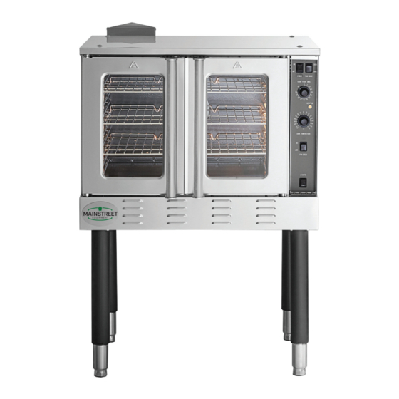
- Page 1 User Manual Convection Ovens Intertek 09/2020 Models: 541CG1N, 541CG1L Please read and keep these instructions. Indoor use only.
-
Page 2: Table Of Contents
Mainstreet Equipment equipment. To ensure optimal performance, we have outlined the following instructions and guidelines in this manual carefully for your review. Mainstreet Equipment declines any responsibility in the event users do not follow the instructions or guidelines stated here. -
Page 3: Product Overview
The automatic ignition system activates in the event of a flameout, and a shutdown device stops the system from trying to ignite the burner(s) after 3 unsuccessful attempts to ensure safety. The electronic automatic thermostat ensures accurate temperatures for precise cooking. SINGLE DECK OVEN Mainstreet Equipment... - Page 4 User Manual DOUBLE DECK OVEN Mainstreet Equipment...
-
Page 5: Oven Stacking Instructions
User Manual STACKING OVEN INSTRUCTIONS *Requires two ovens and stacking kit NOTE We recommend that the stacking is performed by an authorized service agent or installer. Mainstreet Equipment... - Page 6 User Manual BOTTOM OVEN STEP 1: Dismantle the original flue assembly. Install the fixer kit. Install the castors or legs. Mainstreet Equipment...
- Page 7 User Manual STEP 2: Align the top knobs with the notches on the bottom of the oven. Mainstreet Equipment...
- Page 8 User Manual STEP 3: Attach the top and bottom unit with connecting plates and screws. Mainstreet Equipment...
- Page 9 User Manual STEP 4: Attach the stacked flue with screws. Mainstreet Equipment...
- Page 10 User Manual STEP 5: Stacking complete. Mainstreet Equipment...
-
Page 11: Specifications
• Do not install the equipment close to other units that can reach high temperature, as the electrical components could be damaged. A 6” minimum clearance is required from such equipment. Mainstreet Equipment... - Page 12 This equipment is classified as type “A” gas units. 2. This equipment must discharge the combustible products into appropriate hoods. 3. This equipment is not designed to be connected to an evacuation duct for the discharge of combustible products. Mainstreet Equipment...
-
Page 13: Electrical Diagram
User Manual 541S60G24(L/N) ELECTRICAL DIAGRAM FGC100 GAS CONVECTION OVEN Mainstreet Equipment... -
Page 14: Working Instructions & Operation
541080141 COOK/COOL SWITCH 301080141 541080141 HI/LOW SWITCH 301080141 541080141 LAMP SWITCH 301130151 541130151 CHAMBER LAMP 301010262 301120028 541120028 TIMER (N.C.) 301100086 541100086 BUZZER 301100149 541100149 TRANSFORMER 301030169 541030169 THERMOSTAT 301130140 541130140 WORKING INDICATOR 301070047 5411070047 CONNECTOR 301070080 CONNECTOR Mainstreet Equipment... - Page 15 3. To shut down the oven, flip the power switch to the “OFF” position. For a complete shutdown, also open the control panel and remove the right side panel. Turn the manual electric and gas valve to the “OFF” position. Re-attach the right side panel. Mainstreet Equipment...
- Page 16 The appropriate speed is maintain the set temperature, the determined by the type of food indicator will cycle between ON being cooked. and OFF. Oven Interior Light Switch: Press to turn on the light. The light is controlled independently. Mainstreet Equipment...
- Page 17 HI.he fan to run even though the doors are open). For the most rapid cooling, also switch the Fan Speed to HI. 9. When you are done cooking, turn the Cook Temperature Control to the lowest setting (fully counterclockwise) and flip the Power Switch to OFF. Mainstreet Equipment...
-
Page 18: Cleaning & Maintenance
7. Before carrying out any maintenance or repair, disconnect the equipment from the gas network or cut off the mains. Use only original spare parts supplied by Mainstreet Equipment. 8. If the equipment is not going to be used for a long period of time, it is advised to clean the equipment and surrounding areas properly. - Page 19 User Manual PARTS DIAGRAM WHOLE ASSEMBLY: Mainstreet Equipment...
- Page 20 E(20) 20165002014 54165002014 DOOR ASSEMBLY (LEFT) 302201928 541201928 DOOR SHAFT BUSHING 301080079 541080079 DOOR SWITCH 20228051023 54128051023 GUARD TEMPERATURE PROBE 302110578 541110578 OVEN RACK 302110577 541110577 OVEN RACK GUIDE 20165002009 54165002009 FAN COVER 20265002077 54162002077 LEFT SIDE PANNEL Mainstreet Equipment...
- Page 21 User Manual PARTS DIAGRAM COVER ASSEMBLY: Mainstreet Equipment...
- Page 22 20265002037 54165002037 PERIMETER DOOR GASKET RIGHT 20165002004 54165002004 FRONT FRAME ASSEMBLY 20228051023 54128051023 GUARD TEMP PROBE 20265002035 54165002035 PERIMETER DOOR GASKET TOP 2 20265002038 54165002038 PERIMITER GASKET LEFT 20165002003 54165002003 CHAMBER ASSEMBLY 20265002039 54165002039 OVEN RACK GUIDE CLIP Mainstreet Equipment...
- Page 23 User Manual PARTS DIAGRAM CONTROL PANEL: Mainstreet Equipment...
- Page 24 541080141 SWITCH 301150304 541150304 IGNITION MODULE 301120028 541120028 TIMER 301070047 5411070047 TERMINAL BLOCK 301100149 541100149 TRANSFORMER 301030169 541030169 SOLID STATE THERMOSTAT 301130140 541130140 INDICATOR LIGHT 302190015 541190015 HINGE 20265002041 54165002041 SIDE PANEL (CONTROL PANEL) 303124124 541124124 ADHESIVE STICKER Mainstreet Equipment...
- Page 25 User Manual PARTS DIAGRAM DOOR ASSEMBLY: Mainstreet Equipment...
- Page 26 OUTER PANNEL (LEFT DOOR) 20165002012 54165002012 FRAME ASSEMBLY (RIGHT DOOR) 20165002015 54165002015 FRAME ASSEMBLY (LEFT DOOR) 20165002013 54165002013 FRAME ASSEMBLY (DOOR GLASS) 20265002053 54165002053 INNER PANEL (RIGHT DOOR) 20265002061 54165002061 INNER PANEL (LEFT DOOR) 20465002001 54165002001 SEALING STRIP Mainstreet Equipment...
- Page 27 User Manual PARTS DIAGRAM MOTOR: Mainstreet Equipment...
- Page 28 HEAT SHIELD RIVET NUT BOLT 20265002105 54165002105 REINFORCEMENT PLATE BOLT 20265002065 54165002065 HEAT SHIELD 20265002106 54165002106 BUSHING 302201881 541201881 INSULATION PAD 20265002102 54165002102 BAFFLE 302202143 5412021413 MOTOR MOUNTING BRACKET 20265002086 54165002086 FIXED FLANGE 301010215 5411010239 TWO SPEED MOTOR Mainstreet Equipment...
- Page 29 User Manual PARTS DIAGRAM MAIN GAS PIPE: Mainstreet Equipment...
- Page 30 54165002085 FIXED PLATE (VALVE) 302220079 54122079 GAS SAFETY VALVE 302220098 54122098 GAS SAFETY VALVE 302060152 541060152 ELBOW 302050076 541050076 BALL VALVE 302060046 541060046 UNION 302060040 541060040 STRAIGHT PIPE 302060151 541060151 ELBOW 20265002084 54165002084 FIXED PLATE (GAS INLET PIPE) Mainstreet Equipment...
- Page 31 PARTS DIAGRAM INLET GAS PIPE: PART CODE OUR ITEM # DESCRIPTION 302150177 541155177 ORIFICE- NO HOLE 302180512 541180512 MANIFOLD 302200620 541200620 TEST PLUG 302190014 541190014 STRAIGHT PIPE 302140077 541140077 STRAIGHT CONNECTOR 302140079 541140079 COMPRESSION RING 302140080 541140080 COMPRESSION NUT Mainstreet Equipment...
- Page 32 User Manual PARTS DIAGRAM BURNER ASSEMBLY: Mainstreet Equipment...
- Page 33 OUR ITEM # DESCRIPTION 302220004 541220004 FLAME SENSOR 20265002071 54165002071 BURNER 20265002073 54165002073 FIXED PLATE (PROBE) 20265002072 54165002072 PRESSING PLATE (BURNER) 20265002068 54165002068 FLAME SPREADING PLATE 20265002069 54165002069 FIXER (IGNITER) 302170039 5411170039 SURFACE IGNITER 20265002067 54165002067 BRACKET (BURNER) Mainstreet Equipment...
Need help?
Do you have a question about the 541CG1N and is the answer not in the manual?
Questions and answers
How can I get my oven serviced?