Table of Contents
Advertisement
Advertisement
Table of Contents

Related Manuals for EyeLink 1000 Plus


Summary of Contents for EyeLink 1000 Plus
- Page 1 1000 Plus User Manual ® Desktop, LCD Arm, Tower, Primate and Long Range Mounts Remote, 2000 Hz and Fiber Optic Camera Upgrades Version 1.0.12 Copyright ©2013-2017, SR Research Ltd. EyeLink is a registered trademark of SR Research Ltd., Mississauga, Ontario, Canada...
- Page 2 Read instructions before use. For indoor use only. Intertek Safety Mark: Compliance of this product with applicable standards is certified by Intertek, an independent testing agency. Separate electrical and electronic collection. Illuminators comply with 60825-1 or 62471 safety standards. Refer to Chapter 6 of the User CLASS 1 LED DEVICE Manual.
- Page 3 Caution – Using controls or adjustments or performance of procedures other than those specified herein may result in hazardous radiation exposure. Refer to Chapter 6 of User Manual This product complies with FDA performance standards for laser products, except for deviations pursuant to Laser Notice No.
-
Page 4: Table Of Contents
2.4.8 Record Screen ....................48 Status Panel ..................54 Mouse Simulation Mode ..............55 An EyeLink 1000 Plus Tutorial: Running an Experiment ........56 The Camera Setup Screen ..............57 Participant Setup ................58 3.2.1 Desktop Mount Participant Setup, Monocular ..........59... - Page 5 Recording EDF Files ................101 4.2.1 Recording from the EyeLink 1000 Plus Host PC ........101 4.2.2 Recording from the EyeLink API or SR Research Experiment Builder ..101 The EyeLink On-Line Parser .............. 101 4.3.1 Parser Operation ..................101 4.3.2...
- Page 6 4.3.7 Fixation Updates ..................104 4.3.8 Other Parameters ..................105 4.3.9 Sample Configurations ................105 4.3.10 Reparsing EyeLink Data Files ..............106 File Data Types ................. 107 4.4.1 Samples ...................... 107 4.4.2 Position Data ....................107 4.4.3 Pupil Size Data .................... 110 4.4.4...
- Page 7 Limited Hardware Warranty .............. 134 Limited Software Warranty ..............135 Copyrights / Trademarks ..............136 Appendix A: Using the EyeLink 1000 Plus Analog and Digital Output Card .. 137 Analog Data Types ................137 Analog Data Quality ................138 Setting up the EyeLink 1000 Plus Analog Card ......... 138 7.3.1...
- Page 8 Figure 1-2: EyeLink 1000 Plus Desktop Mount ..........6 Figure 1-3: EyeLink 1000 Plus Binocular Tower Mount ........6 Figure 1-4: EyeLink 1000 Plus Primate Mount and Diagram of a Typical Setup 7 Figure 1-5: EyeLink 1000 Plus LCD Arm Mount ..........7 Figure 1-6: Typical EyeLink 1000 Plus Long Range Mount Configuration ..
- Page 9 Figure 3-13: Adjust the Chair Height for EyeLink 1000 Plus Tower Mount ..75 Figure 3-14: Focusing the Eye Camera for EyeLink 1000 Plus Binocular Tower Mount ...................... 76 Figure 3-15: Adjusting the Camera Image Orientation ........77 Figure 3-16: Symptoms of Poor Pupil Threshold ..........79 Figure 3-17: Corner Effects Seen with Head Rotation ........
- Page 10 Table 1: EyeLink 1000 Plus Configuration Files ..........20 Table 2: Lens Guide for Different Viewing Distances ........40 Table 3: Table of Recommended Distance from Illuminator ......131 Table 4: Analog Channel Data Assignments for the EyeLink 1000 Plus hardware141 © 2013-2017 SR Research Ltd.
-
Page 11: Introduction
The EyeLink 1000 Plus is truly a multipurpose eye tracking solution. The EyeLink 1000 Plus camera can be affixed to a Desktop Mount that provides highly accurate monocular or binocular data acquisition at up to 2000 Hz (with the 2000 Hz camera upgrade) using a chinrest. -
Page 12: Figure 1-1: Typical Eyelink 1000 Plus Configuration With A Desktop Mount
Figure 1-1: Typical EyeLink 1000 Plus Configuration with a Desktop Mount All configurations of the EyeLink 1000 Plus operate at the unparalleled low variability required for accurate gaze contingent paradigms, and the highly accurate and sensitive operation that careful research demands. EyeLink systems are the only modern equipment to run on a real-time operating system for low variability and near-instant access to eye data measures. -
Page 13: Supporting Documents
1.1 Supporting Documents The EyeLink 1000 Plus User Guide (this document) contains information on using the EyeLink 1000 Plus hardware, the Host PC application, tutorials on participant setup and calibration, and the basics of running an experiment. Information on system safety, maintenance, and storage is also provided. -
Page 14: Eyelink 1000 Plus System Configuration
1.2 EyeLink 1000 Plus System Configuration 1.2.1 Host PC The EyeLink 1000 Plus Host PC performs real-time eye tracking at 250, 500, 1000, or 2000 samples per second while computing true gaze position on the display viewed by the participant. -
Page 15: Display Pc
The Display PC presents stimuli during experiments and, via the Ethernet Link, can control key eye tracking functionality such as calibration, data collection, etc. On-line eye and gaze position can be received from the EyeLink Host PC via the Ethernet link making gaze-contingent paradigms possible. Licenses can be... -
Page 16: Eyelink 1000 Plus Camera Mount Configurations
The EyeLink 1000 Plus is available in five base hardware configurations (Desktop, Tower, Arm, Primate and Long Range Mounts). These configurations differ in the type of mounting used for the EyeLink 1000 Plus high-speed camera and low output infrared illuminator module. The operation of the Long Range Mount requires an additional Fiber Optic Camera Head. -
Page 17: Figure 1-4: Eyelink 1000 Plus Primate Mount And Diagram Of A Typical Setup
Figure 1-4: EyeLink 1000 Plus Primate Mount and Diagram of a Typical Setup The EyeLink 1000 Plus Primate Mount (Figure 1-4 left) houses the camera and an infrared illuminator in a compact bracket that can be affixed to a vertical surface such as a primate chair. -
Page 18: Figure 1-6: Typical Eyelink 1000 Plus Long Range Mount Configuration
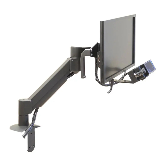
The EyeLink 1000 Plus LCD Arm Mount (Figure 1-5) is a fully adjustable arm holding a 17” LCD monitor with the camera and illuminator mounted beneath it. When fixed on a sturdy table the entire apparatus can be moved in place in... -
Page 19: System Specifications
1.3 System Specifications 1.3.1 Operational / Functional Specifications Desktop and LCD Arm Mounts Tower Mount Base Remote Tracking /Primate Mount System (Remote Camera Upgrade required) Down to 0.15° (0.25° to 0.5° typical) 0.25-0.5° typical Average Accuracy Monocular: 250,500,1000,2000 Hz Monocular: 250,500,1000 Hz Sampling rate Binocular: 250,500,1000,2000 Hz Binocular: 250,500,1000 Hz... -
Page 20: Physical Specifications
1.3.2 Physical Specifications Physical Anodized aluminum enclosure. GL (EyeLink 1000 Plus Standard thread (¼”-20) centered on optical axis from 3 sides. Camera) M8 thread on front for DM and AM mounts. Power requirements: +12VDC, 800 mA for camera alone, 1.8A maximum when used with illuminator(s). - Page 21 CLASS 1 LED DEVICE IEC 60825-1 (Ed. 1.2:2001) NOTE: This equipment has been tested and found to comply with the limits for a Class A digital device, pursuant to part 15 of the FCC Rules. These limits are designed to provide reasonable protection against harmful interference when the equipment is operated in a commercial environment.
-
Page 22: Eyelink 1000 Plus Host Software
• 2.1 Web UI Interface The Web User Interface (Web UI) is a tool supplied with the EyeLink 1000 Plus eye tracker that allows users to access files from the Host PC, configure eye tracker settings, and perform Host software updates. This tool can be run on both the Host PC and the Display PC. -
Page 23: Figure 2-1: File Manager Screen
Toolbar – this contains a list of buttons that perform actions on the currently selected files/folders. From left to right, the buttons on the toolbar are: Tracker Clicking on this icon will start the EyeLink 1000 Plus Host application if the camera is properly powered up and connected. Configuration Switches to the Configuration interface, allowing users to change some of the tracker settings. - Page 24 Note: If you are using a version of Host Software before 5.01, you will need to press the power button of the host PC after EyeLink 1000 Plus Host Software © 2013-2017 SR Research Ltd.
- Page 25 The Tree View panel can be shown or hidden by clicking on the “Show/Hide Tree View” button in the toolbar. The size of the Tree View/Folder View windows EyeLink 1000 Plus Host Software © 2013-2017 SR Research Ltd.
- Page 26 (e.g., cut, copy, paste, delete, rename, download, and eject). Not all operations are supported for all files/folders. These actions can also performed by clicking on the appropriate buttons in the application toolbar. EyeLink 1000 Plus Host Software © 2013-2017 SR Research Ltd.
-
Page 27: Configuration Tool
From left to right, the buttons on the toolbar are: Tracker Clicking on this icon will start the Host application if the EyeLink 1000 Plus camera is properly powered up and connected. EyeLink 1000 Plus Host Software © 2013-2017 SR Research Ltd. - Page 28 This brings up the current document. Configuring screen settings. To correctly compute visual angle, saccade amplitude, and eye velocity, the EyeLink 1000 Plus eye tracker needs to know the physical characteristics of your setup. Any time you change your physical configuration (for example, if a new monitor is used, if the eye-to-screen viewing distance is changed, etc.), you should use the Screen Settings configuration tool...
-
Page 29: Tracker Initialization Files
(*.INI) or by sending commands from the Display PC via the Ethernet link. The configuration files are loaded by the EyeLink 1000 Plus eye tracker from the directory that contains the tracker program (\ELCL\EXE). -
Page 30: Running Web Ui On A Computer Other Than The Host Pc
The Host PC displays the Web UI interface when you close the Host application (by clicking on the “Exit EyeLink” button in the Offline screen or by pressing CTRL+Alt+Q keys together), or when there is an issue in starting the eye tracker. -
Page 31: Starting The Host Application
2.2 Starting the Host Application Figure 2-2: Booting into the EyeLink Partition Make sure you have plugged in the power supply of the EyeLink 1000 Plus camera, and connected the camera to the correct Ethernet port on the Host PC using the network cable supplied with the system. -
Page 32: Modes Of Operation
Camera Setup view of the Host application. Please make sure you are using the latest version of the EyeLink 1000 Plus Host software. The version of the Host software that is being used will be displayed on the Splash screen as well as on the lower right corner of the Offline screen. -
Page 33: Eyelink 1000 Plus Host Pc Navigation
Host PC. Detailed operation instructions can be found in Chapter 7 of this manual. b) File Output. Eye data are available in the EyeLink EDF file format (see Chapter 4 “Data File”). This can be converted to an ASCII file using the EDF2ASC conversion utility or analyzed with EyeLink Data Viewer. -
Page 34: Camera Setup Screen
Figure 2-3: EyeLink 1000 Plus Host PC Application Overview Each of the modes shown in Figure 2-3 has a special purpose. Where possible, each screen has a distinctive appearance. Menus of key options for navigation and setup are provided on the right-side of the screens. The thumbnail images of the eyes are displayed at the lower left corner of most screens and a status bar at the bottom. - Page 35 2.4.1.1 Camera Setup Screen Purpose This is the central screen for most EyeLink 1000 Plus setup functions. From this screen, the view from the camera can be optimized and the pupil and corneal reflection (CR) detection threshold or biases can be established. The eye to be tracked, tracking mode, pupil-fitting model, search limits and display options can be set.
- Page 36 Keyboard Shortcuts: A = align the search limit box around eye position Power level of the illuminators for the head-stabilized Desktop modes (100%, 75%, 50%) and the Remote Mode (100%, 75%). Keyboard Shortcuts: I = change illuminator power level. EyeLink 1000 Plus Host Software © 2013-2017 SR Research Ltd.
- Page 37 CR thresholds and status are displayed beneath the camera image. In the Remote Mode, bias values for pupil and CR thresholds are displayed. Shows the camera-target distance in millimeters and target threshold value (Remote Mode only). EyeLink 1000 Plus Host Software © 2013-2017 SR Research Ltd.
- Page 38 Click to go to the ‘Output’ screen, from which a Recording session can be conducted. This is most useful when using the EyeLink 1000 Plus in the standalone mode. Keyboard Shortcuts: O = go to ‘Output’ screen Click to go to the ‘Set Options’ screen Keyboard Shortcuts: S = go to ‘Set Options’...
- Page 39 Display PC. Keyboard Shortcuts: D = go to Drift Check screen Click to go to the Video Setup screen. See “EyeLink Video Overlay Option User’s Manual” for details. This button is will be displayed only if the “Enable Overlay” button is turned on in the Set Options screen.
-
Page 40: Offline Screen
Select both eyes for recording Toggle Pupil only or Pupil-CR mode selection (may be locked) Toggle Ellipse and Centroid pupil position algorithm Select sampling rate of EyeLink recording Toggle search limit box on or off SHIFT and If search limits are enabled, these keys can be used to move cursor keys the position of the search limits. -
Page 41: Figure 2-5: Example Offline Screen
Click to go to the ‘Output’ screen, from which you can start a manual Recording session. Keyboard Shortcuts: O = go to ‘Output’ screen Click for access to a variety of EyeLink 1000 Plus options and settings on the ‘Set Options’ screen. Keyboard Shortcuts: S = go to ‘Set Options’... -
Page 42: Set Options Screen
Figure 2-6: Example Set Options Screen 2.4.3.1 Set Options Screen Purpose The Set Options screen allows many EyeLink 1000 Plus tracker options to be configured manually. This is useful when doing manual recording sessions in EyeLink 1000 Plus Host Software... - Page 43 Display PC using the EyeLink API, or to override or manipulate options not set by the Display PC application. Ideally, all settings to be crucially controlled are set by the Display PC application at runtime via a set of API calls.
- Page 44 GAZE is screen gaze x, y; HREF is head referenced-calibrated x, y. See section 4.4.2 for description of the data types. Keyboard Shortcuts: E = alternate between Gaze and HREF settings EyeLink 1000 Plus Host Software © 2013-2017 SR Research Ltd.
- Page 45 Each increase in filter level reduces noise by a factor of 2 to 3. Keyboard Shortcuts: F2 = alternate between filter levels for the EDF file Note: Data presented in EyeLink Data Viewer uses the File Sample Filter. SR Research Ltd recommends leaving this value set to EXTRA.
- Page 46 For the Primate Mounts and monocular-only Tower Mount, the available configurations are shown below. Binocular recordings are supported in the Primate mount. EyeLink 1000 Plus Host Software © 2013-2017 SR Research Ltd.
- Page 47 Record gaze position data in the EDF file. See section 4.4.2.3 for description of GAZE data type. Keyboard Shortcuts: G = toggle Gaze Position record on/off Record EyeLink button state and change flags, in the EDF file. Keyboard Shortcuts: B = toggle Button Flags record on/off EyeLink 1000 Plus Host Software ©...
- Page 48 Record external device data (from the parallel port or EyeLink Analog Card) on each sample, in the EDF file. Keyboard Shortcuts: I = toggle Input Port Data record on/off Click to view previous screen. Keyboard Shortcuts: ESC= Previous Screen Click to view Camera Setup screen.
- Page 49 Load default configuration (DEFAULTS.INI) 2.4.3.4 Lens Guide for Different Viewing Distances The EyeLink 1000 Plus eye tracker has a versatile camera that can be fit with different lenses to accommodate different eye-to-camera distances. The table below indicates recommended lenses for different mounts and distances. The...
-
Page 50: Calibrate Screen
(Long Handle or Large Wheel) 35 mm 50-70 cm 60-70 cm 50 mm 70-100 cm 75 mm 100-150 cm Table 2: Lens Guide for Different Viewing Distances 2.4.4 Calibrate Screen EyeLink 1000 Plus Host Software © 2013-2017 SR Research Ltd. -
Page 51: Figure 2-7: Example Calibrate Screen
The eye to be calibrated as well as the calibration type (as defined in the Set Options screen or via the EyeLink API) is indicated beside the camera images at the bottom of the screen. The calibration status and calibration target currently being presented are indicated at the bottom right of the screen. - Page 52 Function Help screen Camera setup Automatic calibration set to the pacing interval selected in Set Options menu. (Auto trigger ON). EyeLink accepts current fixation if it is stable. During Calibration ENTER or Spacebar Begin calibration sequence or accepts calibration value given.
-
Page 53: Validate Screen
If ‘Auto Trigger’ is not enabled, you’ll need to accept the target fixation manually. If the accuracy at a fixated position is not acceptable, you may choose to perform a Calibration again and then recheck fixation accuracy by revalidating. EyeLink 1000 Plus Host Software © 2013-2017 SR Research Ltd. - Page 54 Help screen Terminate validation and go back to camera setup Automatic validation set to the pacing selected in Set Options menu. (Auto trigger ON). EyeLink accepts current fixation if it is stable. During Validation (First Point) Exit to Camera Setup (Following Points) Restart Validation.
-
Page 55: Drift Check/Drift Correct Screen
The Drift Check/Drift Correct screen displays a single target to the participant and then measures the difference between the computed fixation position and the current target. For EyeLink 1000 Plus, the default configuration leaves the calibration model unmodified. The purpose therefore, is to check whether the model has become grossly invalidated. -
Page 56: Output Screen
EyeLink 1000 Plus eye tracker, the default behavior in the pupil-CR mode is to report the calculated fixation error without altering the calibration map in any way. Therefore the procedure is better viewed as a “Drift Checking” procedure in the EyeLink 1000 Plus, though a true Drift Correction can be easily enabled (by toggling on the “Apply Correction”... -
Page 57: Figure 2-10: Example Eyelink 1000 Plus Output Screen
Ethernet link. Manual recording may be terminated by switching back to the OUTPUT screen. Be sure to close the data file before closing the tracker application. Figure 2-10: Example EyeLink 1000 Plus Output Screen 2.4.7.2 Output Screen Main Functions Click to go to the Previous screen Click to go to the ‘Camera Setup’... -
Page 58: Record Screen
Any graphics drawn on the idle-mode screen are re-displayed on the screen to be used as a reference for the real-time gaze-position cursor. The gaze cursor view is only useful when the EyeLink system’s built-in calibration routines have been used for gaze position calculation. -
Page 59: Figure 2-11: Example Record Screen (Gaze Cursor View)
Figure 2-11: Example Record Screen (Gaze Cursor View) Figure 2-12: Example Record Screen (Plot View) EyeLink 1000 Plus Host Software © 2013-2017 SR Research Ltd. - Page 60 For the ease of adjustments, user may select one eye trace at a time. The gain and offset adjustments can be done by using the ⇑ and ⇓ buttons in the “Gain” and EyeLink 1000 Plus Host Software © 2013-2017 SR Research Ltd.
- Page 61 Select zooming level (or use ALT + ⇑ and ALT + ⇓ keys). These buttons will only be available when the plotting data type is Gaze, Angle, or HREF. Keyboard Shortcuts: ALT + ⇑/⇓ = adjust zooming levels EyeLink 1000 Plus Host Software © 2013-2017 SR Research Ltd.
- Page 62 < or > Change plot speed Pause or resume plotting (also marks) Add a rewinding marker Rewind to marker or start HOME Clear all data Undo last view or gain/offset change. EyeLink 1000 Plus Host Software © 2013-2017 SR Research Ltd.
- Page 63 -4 volts. Repeat steps 5 and 6 for fine tuning. 7) Once you are happy with the adjustments, toggle off the “ADJ” button for the eye trace so you will not accidentally modify the values. EyeLink 1000 Plus Host Software © 2013-2017 SR Research Ltd.
-
Page 64: Status Panel
For the Remote Mode, status of target tracking is also provided. Figure 2-14: EyeLink 1000 Plus Status Panel For both the Pupil and Corneal Reflection status reports, the left Status Panel column corresponds to the left eye and the right column corresponds to the EyeLink 1000 Plus Host Software ©... -
Page 65: Mouse Simulation Mode
200 msec. 2.6 Mouse Simulation Mode You can use a mouse on the EyeLink 1000 Plus Host PC to simulate an eye to practice calibration and tracking alone or to test experiments during development if a test participant is not available. -
Page 66: An Eyelink 1000 Plus Tutorial: Running An Experiment
If the EyeLink host software is not yet running on the Host PC, start it by clicking on the EyeLink logo at the top-left corner of the File Manager (see section 2.2 “Starting the Host Application”... -
Page 67: The Camera Setup Screen
Display PC. The advantage of the Display PC based control is that it allows the operator to work near the participant, or for self-setup. We will perform most of the EyeLink 1000 Plus setup by using the Host PC keyboard. -
Page 68: Participant Setup
Since no menus appear on the Display PC, you will have to be able to see the Host PC display as well. NOTE: Ideally, to prevent small drifts in thresholds, EyeLink 1000 Plus electronics should be powered on for about 10-15 minutes before starting the recording. -
Page 69: Desktop Mount Participant Setup, Monocular
The EyeLink Desktop Mount can be configured to track monocular or binocular eye movements up to 2000 Hz depending on the system model and licensing. Take the following steps if you plan to set up the EyeLink 1000 Plus Desktop Mount for monocular tracking. -
Page 70: Figure 3-2: Parts Of The Eyelink 1000 Plus Desktop Mount
7) Start the EyeLink Host PC application and go to the “Set Options” Screen. Click “Configuration” and make sure the option “Desktop ~ Stabilized Head ~ Monocular ~ 35mm lens | MTABLER” is selected. 8) Now go to the camera setup screen. Set the “Illuminator Power” level in the lower-left corner of the screen to 75%. -
Page 71: Figure 3-3: Camera Setup With Participants Wearing Glasses
If a turquoise (CR signal) appears near the pupil, the best focus will minimize the size of this colored circle. An EyeLink 1000 Plus Tutorial: Running an Experiment © 2013-2017 SR Research Ltd. -
Page 72: Desktop Mount Participant Setup, Binocular
Therefore, the current section just highlights the steps that are unique to the binocular tracking. 1) Start the EyeLink host application and click “Set Options” button. Check the “Configuration” is set to “Desktop ~ Stabilized Head ~ Binoc/Monoc ~ 35 mm lens | BTABLER”. -
Page 73: Desktop Mount Participant Setup, Monocular Remote Mode
Now focus the camera and continue with section 3.3 “Setting Pupil Threshold”. 3.2.3 Desktop Mount Participant Setup, Monocular Remote Mode The Remote Mode of the EyeLink 1000 Plus eye tracker is designed for applications where a chin rest or head mount is not desirable or perhaps even possible (e.g., patient work, gerontology, infants/young children, etc.). - Page 74 If your system is licensed to use the EyeLink Remote Mode, take the following steps to set up the camera and perform image adjustments. 1) For the Remote Mode, attach the 16 mm lens (shipped standard with a short adjustable focus arm or small wheel) to the camera. The system by default is configured to use 16 mm remote lens.
-
Page 75: Figure 3-6: Camera Setup Screen With The Monocular Remote Mode
If the target sticker is placed too much towards the temporal side An EyeLink 1000 Plus Tutorial: Running an Experiment © 2013-2017 SR Research Ltd. - Page 76 “DIST FAR” error. If the tracked eye does not appear centered in the global camera view, the angle of the Desktop Mount may be adjusted slightly. Target is Good Status Panel An EyeLink 1000 Plus Tutorial: Running an Experiment © 2013-2017 SR Research Ltd.
-
Page 77: Figure 3-7: Eyelink Remote Target Placement
This is generally an indication that the monitor is placed too close to the participant (i.e, a large viewing angle), forcing them to rotate their eye beyond the trackable range of the system. An EyeLink 1000 Plus Tutorial: Running an Experiment © 2013-2017 SR Research Ltd. -
Page 78: Figure 3-8: Pupil And Cr Thresholds And Bias Values
12) In the zoomed camera image, the threshold values for pupil and corneal reflection are displayed under the camera image. Unlike other tracking modes of the EyeLink 1000 Plus eye tracker, these threshold values are automatically updated in the Remote Mode. The number beside the pupil threshold value is pupil bias –... - Page 79 16) Version 5.03 of the EyeLink host software implements exposure control, which is used to adjust the brightness of the camera image when the eye-to- camera distance changes and to improve the dynamic range of the EyeLink 1000 Plus camera. Unlike other head-supported tracking modes, the...
-
Page 80: Figure 3-9: Status Panel Pupil Size Information
For reliable tracking, both dots should stay within the red box. Adjustment of the camera’s view of the participant is advised if you experience difficulties in tracking them. An EyeLink 1000 Plus Tutorial: Running an Experiment © 2013-2017 SR Research Ltd. -
Page 81: Desktop Mount Participant Setup, Binocular Remote Mode
3.2.4 Desktop Mount Participant Setup, Binocular Remote Mode Version 5.03 or later of the EyeLink 1000 Plus host software supports binocular tracking in the Remote Mode up to 1000 Hz. Binocular recording in the Remote Mode is essentially the same as the monocular recording described in the previous section. -
Page 82: Lcd Arm Mount Participant Setup
Remote Mode 3.2.5 LCD Arm Mount Participant Setup The EyeLink 1000 Plus LCD Arm Mount works in conjunction with highly accurate recording with the head stabilized or with head free recording in the Remote Mode (licensing required). Regardless of the recording mode, positioning the Arm Mount requires similar considerations. -
Page 83: Tower Mount Participant Setup, Monocular Or Binocular
Tower Mount. NOTE: Please check the height of the EyeLink 1000 Plus Tower before having a participant seated - ideally this should have the top of the display at about the same height as the forehead rest. The Tower height adjustment should only An EyeLink 1000 Plus Tutorial: Running an Experiment ©... -
Page 84: Figure 3-12: Parts Of The Eyelink 1000 Plus Tower Mount
To run the tracker in the binocular Tower mount configuration, start the EyeLink host application and go to the Set Options screen. Make sure the “Configuration” is set to “Tower Mount (Binocular) ~ Stabilized Head ~ Binoc/Monoc ~ 25 mm | BTOWER”. Press the Enter key to go back to the camera setup screen. -
Page 85: Figure 3-13: Adjust The Chair Height For Eyelink 1000 Plus Tower Mount
(depending on the shape of the glasses and reflectiveness of the glasses) and therefore you may not be able to track the participant even after adjusting the mirror angle; the EyeLink 1000 Plus Desktop Mount has better compatibility with glasses. -
Page 86: Primate Mount Participant Setup, Monocular Or Binocular
85 x 65 mm 3.2.8 Long Range Mount Participant Setup, Monocular or Binocular The EyeLink 1000 Plus Long Range Mount can be configured to track monocular eye movements at up to 2000 Hz, or binocular movements up to 1000 Hz per eye depending on camera licensing. -
Page 87: Figure 3-15: Adjusting The Camera Image Orientation
The EyeLink 1000 Plus Installation Guide provides information for setting up the Long Range Mount generally as well as specifically with particular types of MEG scenarios, and MRI scanner and head coil combinations. The Long Range Mount should only need to be set up once for a given eye tracking setting. - Page 88 Discussion of configuring and using the External Camera Setup feature can be found in the Experiment Builder User Manual (version 1.10.165 or later). An EyeLink 1000 Plus Tutorial: Running an Experiment © 2013-2017 SR Research Ltd.
-
Page 89: Setting Pupil Thresholds
If the eyeglasses have an anti-reflective coating, image contrast may be poor and pupil tracking may be noisy. These reflections are automatically reduced as much as possible by the EyeLink system; however please be advised that not every participant with glasses will be trackable. -
Page 90: Figure 3-17: Corner Effects Seen With Head Rotation
If the pupil threshold or corneal thresholds are too high, try reducing the illuminator output or increase the eye-to-camera distance. EyeLink 1000 Plus Desktop and LCD Arm Mount Users: If the pupil crosshair flickers on and off or becomes missing even though the pupil is clearly visible, then the pupil size may be too small. -
Page 91: Setting The Corneal Reflection (Cr) Threshold
3.4 Setting the Corneal Reflection (CR) Threshold For EyeLink 1000 Plus, the “Tracking mode” should almost always be set to pupil-CR mode, regardless whether you plan to use head stabilization or not. The pupil-only mode should only be used with a bite bar. The corneal reflection, if present, is identified by a circular shape in turquoise. -
Page 92: Search Limits
3.5 Search Limits The EyeLink 1000 Plus eye tracker provides a “Use Search Limits” option. If enabled, it draws a red box or ellipse in the global view of the camera image to reduce the area of the camera image that is searched to locate the pupil position. -
Page 93: Calibration
Remote tracking exclusively uses the Ellipse-Fitting pupil tracking method. 3.7 Calibration The preceding steps set up the EyeLink 1000 plus eye tracker to track the positions of the pupil and CR of the selected eye. Almost all eye-movement research requires information on the participant's point of gaze on a display of visual information, such as a screen of text. - Page 94 The proper timing is best learned by watching the gaze cursor during validation (discussed later). The EyeLink system helps prevent improper triggering by locking out the ↵ key and spacebar if the eye is moving. Sometimes the ↵ key will be locked out because of poor camera setup, with the pupil noisy or undetected in some positions.
-
Page 95: Figure 3-19: Calibration Grid
If automatic sequencing has been enabled, targets will be presented and fixations collected without further intervention. Each time a new target is displayed, the participant should quickly make a saccade to it. The EyeLink 1000 Plus system detects these saccades and the fixation following, producing an automated sequencing system. - Page 96 (the latter only in Remote Mode) signals and thus will indicate any lapses in data collection. In normal operation, the indicators should all be green. Should any of the indicators display a color other than green and the An EyeLink 1000 Plus Tutorial: Running an Experiment © 2013-2017 SR Research Ltd.
-
Page 97: Validation
During validation, targets are again presented to the participant in a random order, similar to the calibration procedure. When the participant fixates these, An EyeLink 1000 Plus Tutorial: Running an Experiment © 2013-2017 SR Research Ltd. - Page 98 The gaze-position error comes largely from errors in fixation data gathered during the calibration/validation, which come from two sources: the eye- tracking system and physiological eye-movement control. The EyeLink system has extremely low pupil-position noise and very high resolution, and corrects for small head motion during calibration and recording.
-
Page 99: Improving Calibration Quality
(or close-to- horizontal) lines and three parallel vertical (or close-to-vertical) lines. Redo the calibration or camera setup if you do not see this. An EyeLink 1000 Plus Tutorial: Running an Experiment © 2013-2017 SR Research Ltd. -
Page 100: Recording Gaze Position
Pressing the “Output” button or the ‘O’ key from the Camera Setup screen will display the Output menu, where EyeLink Data Files (*.EDF) can be opened and closed, and analog output (if installed) can be controlled. TRACK.EXE automatically opens a data file ‘SDEMO.EDF’, but you can change this by opening a new file in this menu. -
Page 101: Drift Checking And Drift Correction
Therefore, the default drift correction behavior of the EyeLink 1000 Plus system when in pupil-CR mode is to only report the calculated fixation error from the drift correction procedure and to not actually adjust the calibration map in any way. -
Page 102: Online Drift Correction
FINAL.INI or sent across the link. The default setting in the behavioral laboratory setting is to turn ON the disabling of the drift correction when the CR is being used on the EyeLink 1000 Plus. We are turning this disabling OFF so that the drift correct adjustment will take place. -
Page 103: Figure 3-20: Performing A Drift Correction Using Mouse Click
The EyeLink 1000 Plus has two possible online drift correction methods: Drift Correct to Mouse-Click Position and Drift Correct to a Fixed Location. These methods are described in detail below, followed by a list of shared parameters controlling the drift correction behavior. - Page 104 3.11.2.2 Online Drift Correct to a Fixed Location Using Online Drift Correct to a Fixed Location requires that the coordinate that the participant should fixate is set using an EyeLink command (or predefined in the software). When a drift correction is to be applied the experimenter initiates the correction by clicking the “Drift Corr”...
-
Page 105: Exiting The Host Application
= 5.0 3.12 Exiting the Host Application You can now close the EyeLink 1000 Plus tracker program. Press the key combination ‘CTRL+ALT+Q’ from any point in the Host PC tracker program to exit to the File Manager. You can also go to the Offline screen and click on the “Exit EyeLink”... -
Page 106: Experiment Practice
Host PC and the power to the camera at the end of the day. 3.14 Experiment Practice The TRACK.EXE program is the most flexible way to practice the EyeLink 1000 Plus setup, allowing almost any sequence of actions to be performed. In real experiments, the sequence of actions is much more defined. -
Page 107: Next Steps: Other Sample Experiments
“Start -> All Programs -> SR Research -> EyeLink Examples -> C Examples -> GDI Graphics (or SDL Graphics)” menu item. On Mac OS X, the examples can be run from “Applications -> EyeLink -> SampleExperiments -> SDL”. - Page 108 Experiment to show a single line of text, illustrating the use of runtime interest area. TextPage Experiment to show a full screen of text using a multi-line text An EyeLink 1000 Plus Tutorial: Running an Experiment © 2013-2017 SR Research Ltd.
- Page 109 Illustrates the creation of a simple experiment for saccade/anti- saccade research. Pursuit Illustrates several kinds of sinusoidal movement in a pursuit task. Video Illustrates creating an experiment displaying video clips using XVD codec. An EyeLink 1000 Plus Tutorial: Running an Experiment © 2013-2017 SR Research Ltd.
-
Page 110: Data Files
4. Data Files The EDF file format is used by the EyeLink tracker and supporting applications to record eye-movements and other data. It is designed to be space-efficient and flexible, allowing for complete records of experimental sessions and data. It adapts to monocular and binocular recording, with backwards-compatibility for future enhancements. -
Page 111: Recording Edf Files
Special provisions must be made to display the calibration pattern in these situations. By using the EyeLink 1000 Plus tracker’s Output Screen, files may be opened and closed, and recording sessions may be started and stopped. Refer to Chapter 2 of this manual “EyeLink 1000 Plus Host Application Operation”... -
Page 112: Parser Limitations
Then view the EDF file with EyeLink Data Viewer or convert the EDF file to an ASC file to see the correspondence between the sample data and the events identified by the parser. -
Page 113: Parser Data Type
The eye-movement data can then be viewed with EyeLink Data Viewer with saccades and blinks overlaid, to confirm the parsing accuracy. Once correct parameters are determined, they can be set by the EyeLink 1000 Plus commands over the link as part of the experimental setup, or the EyeLink 1000 Plus configuration file PARSER.INI (REMPARSE.INI for the EyeLink Remote) or... -
Page 114: Pursuit Thresholds
70°/sec. While acceleration can be used to detect these saccades, velocity data must also be used for reliable detection of all saccades. The EyeLink 1000 Plus parser raises the saccadic velocity threshold during pursuit by the average velocity over the last 40 milliseconds. -
Page 115: Other Parameters
= 50 fixation_update_accumulate = 50 4.3.8 Other Parameters The EyeLink 1000 Plus PARSER.INI configuration file contains other commands that configure the parser. These are of several types: Verification delays. These set the time in milliseconds that the parser •... -
Page 116: Reparsing Eyelink Data Files
Occasionally, researchers may wish to evaluate the data using different parametric definitions. The EyeLink 1000 Plus Host PC software supports reparsing existing EyeLink 1000 Plus EDF files. To do this, save the desired saccade detection configurations into a new .INI file. Copy the original EDF file to the current EyeLink host directory (“\ELCL\EXE”... -
Page 117: File Data Types
Other types of sample data are discussed in greater detail below. 4.4.2 Position Data Eye position data is produced by the EyeLink 1000 Plus tracker every 0.5, 1, 2 or 4 milliseconds depending on the tracking mode and speed set. It is then... - Page 118 Pupil position is reported in integer values, with 200 to 400 units per visual degree. When a calibration has not been performed, the EyeLink system cannot convert pupil data to the more useful data types. Raw pupil position is useful when auto-sequencing calibrations, or when the application wishes to perform its own calibration.
- Page 119 (see below). A typical resolution is about 36 pixels per degree for an EyeLink 1000 Plus setup in which the distance between the participant's eyes and the display is twice the display's width, and the screen resolution is set to 1024 by 768.
-
Page 120: Pupil Size Data
4.4.3 Pupil Size Data Pupil size is also measured by the EyeLink 1000 Plus system, at up to 2000 samples per second depending on your tracker version. It may be reported as pupil area, or pupil diameter. -
Page 121: Events
300 bytes. Messages are created by the application software, and forwarded over the link to the EyeLink tracker, which timestamps the data and writes it to the EDF file. The application does not need precise time keeping, since link delays are usually very low (on the order of 1 or 2 milliseconds). -
Page 122: Eye Movement Events
4.5.3 Eye Movement Events Events are generated by the EyeLink 1000 Plus tracker in real-time from the eye-movement data stream. These provide an efficient record of the data in a form ready to use for most types of eye-movement research. The use of events simplifies the analysis of sample data as well. - Page 123 Other data is given on following SAMPLES, EVENTS, PRESCALER, etc. lines. 4.5.3.2 Fixations The on-line EyeLink 1000 Plus tracker parser processes eye-position data, identifying saccades and fixations and compiling data on these conditions. For fixations, these data include: The time of the first and last sample in the fixation •...
- Page 124 Some cognitive research may ignore the saccadic data and only use the fixation data produced by the EyeLink 1000 Plus parser. The saccadic data produced for saccades includes: The time of the first and last sample in the saccade •...
- Page 125 The peak and average velocity data for saccades is especially valuable for neuro- psychophysical work. These are the absolute velocities measured as the Euclidean sum of x and y components. The EyeLink 1000 Plus parser computes velocity by use of a multiple-sample moving filter adjusted for different sampling rates.
-
Page 126: Setting File Contents
Setting File Contents The data recorded in samples and events may be set in the EyeLink 1000 Plus configuration file DATA.INI, and maybe overwritten by the settings in LASTRUN.INI and FINAL.INI. As a result, it is preferred to send those commands to the tracker across the link, via the API eyecmd_printf(). -
Page 127: Event Data
The "file_event_filter" command specified what type of events will be written to the EDF file. It may be changed in the DATA.INI file of the EyeLink 1000 Plus tracker, or may be sent over the link. The command is followed by a list of data... -
Page 128: Edf File Utilities
LEFT,RIGHT,FIXATION,SACCADE,BLINK,MESSAGE,BUTTON 4.7 EDF File Utilities A number of utility programs are included in the EyeLink 1000 Plus package, to process and view EDF files. The utility EDF2ASC translates EDF files into text ASC files for processing with user applications. EyeLink Data Viewer is an optional tool that allows displaying, filtering, and reporting the output of EyeLink Data Files. -
Page 129: The Asc File Format
"edf2asc" followed by the name of the file to be translated and any conversion options. Wildcards (* and ?) may be used in the input file name, allowing conversion of multiple EDF files to ASC files with the same name. Optionally, a second file name can be specified for the output ASC file. -
Page 130: Sample Line Format
the sequence of sample timestamps may also be used to determine sample block divisions. For ASC files containing events (and optionally samples), the order of lines is carefully structured. The file begins with a copy of the EDF file's preamble, with each line preceded by "**". - Page 131 Several possible sample line formats are possible. These are listed below. SAMPLE LINE FORMATS Monocular: • <time> <xp> <yp> <ps> Monocular, with velocity • <time> <xp> <yp> <ps> <xv> <yv> Monocular, with resolution • <time> <xp> <yp> <ps> <xr> <yr> Monocular, with velocity and resolution •...
- Page 132 "C" if RIGHT CR missing fifth character is "R" if RIGHT CR recovery in progress 4.9.2.2 Samples Recorded with the EyeLink Remote Data files recorded using the Remote Mode have extra columns to encode the target distance, position, and eye/target status information. The first three columns are: <target x>: X position of the target in camera coordinate (a value from 0 to 10000).
-
Page 133: Event Line Formats
• A message line contains the text of a time stamped message. Message is typically sent to the EyeLink 1000 Plus tracker by an application. It contains data for analysis or timestamps important events such as display changes or participant responses. The <message> text fills the entire line after the timestamp and any blank space following it. - Page 134 be created to monitor any digital input port bit, and may be created by link commands or in the tracker configuration file BUTTONS.INI or FINAL.INI. 4.9.3.3 Block Start & End START <time> <eye> <types> • END <time> <types> RES <xres> <yres> •...
- Page 135 4.9.3.5 Saccades SSACC <eye> <stime> • ESACC <eye> <stime> <etime> <dur> <sxp> <syp> <exp> <eyp> <ampl> <pv> • ESACC <eye> <stime> <etime> <dur> <sxp> <syp> <exp> <eyp> <ampl> <pv> • <xr> <yr> The start of saccades are reported with a SSACC line, which can be eliminated with the EDF2ASC "-nse"...
-
Page 136: Data-Specification Lines
4.9.4 Data-Specification Lines Right before each block of recorded data, a few specification lines are written to the EDF file to report the recording information of the trial such as mount type, sampling rate, filtering level, pupil threshold, and pupil tracking algorithm. RECCFG <tracking mode>... -
Page 137: Processing Asc Files
line is encountered, and setting the appropriate flags when keywords ("LEFT", "VEL", etc.) are encountered in a data specification line. PRESCALER <prescaler> • If gaze-position data or gaze-position resolution is used for saccades and events are used, they must be divided by this value. For EDF2ASC, the prescaler is always 1. - Page 138 into a text buffer (at least 250 characters in size), and to scan the line as a series of tokens (non-space character groups). The first token in each line identifies what the line is: First character in first token Line type <no token>...
-
Page 139: System Care
The EyeLink 1000 Plus Host PC is a dedicated data collection computer for the eye tracker; users are advised not to use that computer for other purposes. -
Page 140: Important Information
The EyeLink DM, AM, PM, and FL series of mounts and illuminators are compliant with current eye safety standards, including the 62471 Lamp Safety standards and the 60825-1 LED safety standard as a Class 1 LED device. -
Page 141: Servicing Information
Illuminator Type Power Level Minimum Distance PM-910 preset 150 mm PM-940 DM-890 High (100%) 500 mm DM-850W Medium (75%) 430 mm DM-940 Low (50%) 350 mm DM-850L High (100%) 650 mm Medium (75%) 450 mm Low (50%) 300 mm Table 3: Table of Recommended Distance from Illuminator In addition to its invisible light output, the illuminators and heatsinks may become warm during operation. -
Page 142: Non-Serviceable Components
WARNING: Opening or modifying camera or illuminators, or power supply substitutions, will void the warranty and may affect the safety compliance of the system. No user-serviceable parts inside - contact SR Research for all repairs. CAUTION: Modification of illuminators, or use of other power supply voltages with this system, may result in excessive exposure to infrared radiation. -
Page 143: Power Supply Replacement
The EyeLink 1000 Plus camera requires a power supply that is rated for 12VDC and 2A or higher. This supply must have a 2.5mm coaxial (“barrel”) power connector (5.5 ×... -
Page 144: Limited Hardware Warranty
EyeLink 1000 Plus High-Speed Camera – Two (2) year parts and labor. EyeLink 1000 Plus Illuminator Module – Two (2) year parts and labor. EyeLink 1000 Plus Head Support System (excluding gel pads) – Two (2) year parts and labor. -
Page 145: Limited Software Warranty
In certain instances, some jurisdictions do not allow the exclusion or limitation of incidental or consequential damages, or the exclusion of implied warranties, so the above limitations and exclusions may not be applicable. WARRANTY SERVICE please contact a SR Research Ltd. For product operation and information assistance Support representative (support@sr-research.com). -
Page 146: Copyrights / Trademarks
6.5 Copyrights / Trademarks EyeLink is a registered trademark of SR Research Ltd. All other company and / or product names are trademarks of their respective manufacturers. Product design and specifications may change at any time without notice. Important Information... -
Page 147: Appendix A: Using The Eyelink 1000 Plus Analog And Digital Output Card
This measurement is related to the tangent of the rotation angle of the eye relative to the head. In the default EyeLink 1000 Plus setup, and for the -5V to +5V output range, it is 5V*tan(angle), measured separately for vertical and horizontal... -
Page 148: Analog Data Quality
7.3 Setting up the EyeLink 1000 Plus Analog Card 7.3.1 Installing Analog Output Hardware To install the analog output card, open the case of EyeLink Host PC, install the card into an empty PCI slot, and secure the rear bracket of the card with the bracket screw. -
Page 149: Connections To Analog Card
- typically this is another computer with an analog input card or an EEG recording system. Figure 7-1 Screw Terminal Panel Pin Mapping Table Appendix A: Using the EyeLink 1000 Plus Analog and Digital Output Card © 2013-2017 SR Research Ltd. -
Page 150: Noise And Filtering
KHz low pass filter, which should settle to 1% in 220 microseconds). 7.4 Digital Inputs and Outputs The digital ports are configured by the EyeLink software with A0-A7 and B0-B7 as inputs, and C0-C7 and D0-D7 as outputs. Digital outputs may be set by the... -
Page 151: Analog Data Output Assignments
7.4.1 Analog Data Output Assignments The EyeLink 1000 Plus hardware outputs analog voltages on 3 to 6 channels, depending on the mode of operation (monocular or binocular) and the analog card configuration. The monocular analog output configuration (set by the command in the ANALOG.INI file) should be used... -
Page 152: Scaling Of Analog Position Data
The following formulas do the conversion in several stages, with R being the voltage range proportion, and S being the proportion of screen width or height. R = (voltage-minvoltage)/(maxvoltage-minvoltage) Appendix A: Using the EyeLink 1000 Plus Analog and Digital Output Card © 2013-2017 SR Research Ltd. -
Page 153: Pupil Size Data
7.6 Timebase and Data Strobe The EyeLink 1000 Plus eye tracker samples eye position every 0.5, 1, 2 or 4 ms and outputs analog data at 2000, 1000, 500, or 250 hz (depending on your tracker setting and system licensing). This combination of fast sampling rate... -
Page 154: Oversampling And Toggle Strobe
Another possibility is to over sample the analog output, by recording the analog outputs at more than twice the EyeLink 1000 Plus sample rate. This will prevent missed samples, but will still result in steps in the data. Recording the...
Need help?
Do you have a question about the 1000 Plus and is the answer not in the manual?
Questions and answers