Table of Contents
Advertisement
Advertisement
Table of Contents

Related Manuals for Re T-one ULS

Summary of Contents for Re T-one ULS
- Page 1 E N G T-one ULS Servo-diameter with TAPER function USER’S MANUAL...
-
Page 3: Table Of Contents
-one ULS Contents Warnings ................................1 Intended use of the device........................... 2 “Taper tension” function ..........................3 “Selematic” function ............................4 Instrument functioning ..........................6 Programming ..............................8 Quick start-up ..............................10 Installation ..............................10 Adjustment mode ............................10 Calibration functions ..........................10 Electrical connection diagrams ........................ - Page 4 -one ULS Function 39 – Remote control ............................20 Function 50 – Braking section 1 percentage (SECT.1) ....................20 Function 51 – Braking section 2 percentage (SECT.2) ....................20 Function 52 – Braking section 3 percentage (SECT.3) ....................21 Function 70 – Type of adjusted output .......................... 21 Function 73 –...
-
Page 5: Warnings
The plant builder may include the present manual in the documentation for plant use. Re S.p.A. reserves the right to update its production and/or manuals without updating products already sold and previous manuals. -
Page 6: Intended Use Of The Device
The instrument features a front panel to control the adjustment parameters and to program and calibrate the instrument itself. The T-one ULS automatic adjustment system is used to update the torque of a brake or clutch based on the diameter value of the reel, by performing a servo diameter open loop adjustment. The “Taper tension”... -
Page 7: Taper Tension" Function
-one ULS “Taper tension” function The “Taper tension” function is normally used to avoid that the material on the reel is too tensioned (or not sufficiently tensioned) as the diameter increases, and vice versa. It allows to change the brake use percentage automatically, according to the diameter of the reel, and it is normally used on the rewinders, but in some cases, it is also useful on the unwinders. -
Page 8: Selematic" Function
(section 1 is always active) whose torque percentages are known. In this way it sizes the brake according to the instantaneous torque requirements. BRAKE RE calipers torque percentages The torque percentage developed by each caliper is shown by the colour found on the actual caliper: SECT.2... - Page 9 CN2 T-One 21 22 24Vdc EV.0 Electro valve pneumatic symbols Electro valve connector rear view EV.1 Electo valve connector rear view CONNECTOR E.V. FORM B IND. PROTECT. CIRCUIT (Code Re E0304072) Rev. 06/18 5/26...
-
Page 10: Instrument Functioning
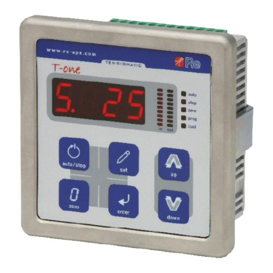
-one ULS Instrument functioning States LEDs Display Bar graphs display General information The front panel features a seven-segments led display with four numbers and two bar graphs displays to display all the adjustment parameters. The keypad allows access to the device programming and calibration. The state led provides information on the instrument functioning state. - Page 11 -one ULS States led Every instrument functioning state is represented by a combination of on or blinking state leds: auto led on regulator in AUTO state (machine running) auto led blinking regulator in ACC state (machine in acceleration ramp) ...
-
Page 12: Programming
-one ULS Programming The following is a summary of the device programming functions available. For a more detailed description, consult § Detailed description of programming functions on page 17. Factory Function Display Function description Value range setting STOP Braking in STOP 0÷100.0 10.0 STOP braking variation percentage... - Page 13 -one ULS To enter the programming environment keep pressed the enter key for about one second: the display shows F.1. To scroll the programming function menu use the up or down keys. To edit function parameters: ▪ select the desired function number; ▪...
-
Page 14: Quick Start-Up
A more detailed description of how each function works is given in § Detailed description of programming functions (page 16). Installation Fit the T-one ULS regulator. Make the electrical connections as illustrated in § Electrical connection diagrams (pages 12-13). Connect the instrument to a power supply. - Page 15 -one ULS press up to move onto the next function. F.34 appears on the display: use this function to set the minimum diameter value; press enter and the function value set is displayed; using the up or down keys set the minimum diameter value; ...
-
Page 16: Electrical Connection Diagrams
-one ULS Electrical connection diagrams The instrument must be connected to the zero potential by using the screw located close to the CN1 contact The connection to ground must be as short as possible 13 14 17 18 19 20 21 22 - + - + Electrical Inputs / Outputs... - Page 17 -one ULS With the “Selematic” function activated The instrument must be connected to the zero potential by using the screw located close to the CN1 contact The connection to ground must be 13 14 17 18 19 20 21 22 as short as possible - + - + Electrical...
-
Page 18: Instrument Inputs / Outputs Description
-one ULS Instrument inputs / outputs description Power supply Pin 1 ( + ); Pin 2 ( - ) The instrument must be supplied with a continuous voltage of 24Vdc. Digital inputs AUTO/STOP Pin 13 The input is active if F.39 = 1. If it’s in the “HIGH”... -
Page 19: Analog Input Ain1
Brake or clutch control It provides a command analog reference (torque adjustment) for a brake/clutch; the analog input of the electro-pneumatic transducer (pneumatic brake) or, using the Re S.p.A. FP25 or TAURUS command board, a magnetic powder brake, must be connected to it. -
Page 20: Detailed Description Of The Programming Functions
-one ULS Detailed description of the programming functions Function 1 – Braking in STOP Use this function to set a percentage of the use of the brake/clutch or motor when the machine is stationary (STOP state). Press enter to access the function and the function value set is displayed. ... -
Page 21: Function 11 - Taper Start Diameter
-one ULS Function 11 – Taper start diameter Use this function to set the diameter from which the Taper function will be active; see § “Taper tension” function on page 3. Press enter to access the function and the function value set is displayed. ... -
Page 22: Function 18 - Inertia Contribution In Dec
-one ULS Function 18 – Inertia contribution in DEC The inertia contribution is used to facilitate the stop of the reel in deceleration and it is calculated according to the diameter of the reel. This function lets you set the maximum inertia contribution to add or subtract to the adjustment close to the maximum diameter. -
Page 23: Function 31 - Decimal Point
-one ULS Press up or down to set 0 to use the AIN1 input (0÷10Vdc) or 1 to use the AIN0 input (4÷20mA). Press enter to confirm. Note: AIN0 is a mA input, AIN1 is a 0÷10Vdc input, be sure that the diameter sensor supplies the right signal for the input set. -
Page 24: Function 37 - Setting The Minimum Value Of Remote Set Point
-one ULS Press up or down and set 0 if you desire to control the set point through the keypad or 1 to manage it from analog input. Press enter to confirm. If the remote set point is enabled, position on function 37 and then on function 38 in order to calibrate the analog reference. -
Page 25: Function 52 - Braking Section 3 Percentage (Sect.3)
-one ULS Press enter to access the function and the function value set is displayed. Press up or down and set the desired percentage. Press enter to confirm. Example: if SECT.2 is composed by a BLACK caliper (100%) and a RED caliper (40%) the percentage set in F.51 is 140% (100% + 40%). -
Page 26: Function 77 - Display Brightness
-one ULS Then the instrument exits the programming environment automatically. Function 77 – Display brightness Use this function to regulate the brightness value of the display. Press enter to access the function and the function value set is displayed. ... -
Page 27: Technical Specifications
-one ULS Technical specifications Analog section Inputs For “diameter reference” or “remote setpoint” (see F.30): 1 analog input AIN0: 420mA 1 analog input AIN1: 010V / R=10k Uscite 1 selectable analog output (torque adjustment on brake/clutch): 010V / 10mA max 420mA R =330max load... -
Page 28: Mechanical Dimensions
-one ULS Mechanical dimensions Fixing hole Max thickness: 7mm Rev. 06/18 24/26... -
Page 29: Guarantees
-one ULS Guarantees Re S.p.A. guarantees this device against all defects relative to the materials and manufacturing for a period of 12 months from the date of delivery. Should your device develop operating faults during the guarantee period, please contact the Company’s agent in your country, or, if this is not possible, contact Re S.p.A. -
Page 30: Revision History
-one ULS Revision history Nr. rev. Date Changes 08/06/2018 Reduced the minimum ∆ of diameter inputs 06/18 Rev. 06/18 26/26... - Page 32 Re S.p.A. Controlli Industriali Via Firenze, 3 – 20060 BUSSERO (MI) ITALY Fax (+39) 02 95 03 89 86 Technical support: Tel. (+39) 02 95 24 30.300 - E-mail: support@re-spa.com Sales support: Tel. (+39) 02 95 24 30.200 - E-mail: sales@re-spa.com www.re-spa.com...
Need help?
Do you have a question about the T-one ULS and is the answer not in the manual?
Questions and answers