Table of Contents

Related Manuals for DKS 2351

Summary of Contents for DKS 2351
- Page 1 Owner’s Manual Model 2351 System Expansion Boards DoorKing, Inc. 120 Glasgow Avenue Inglewood, California 90301 U.S.A. Phone: 310-645-0023 Fax: 310-641-1586 www.doorking.com P/N 2351-065 REV G, 12/07 Copyright 2001 DoorKing, Inc. All rights reserved.
- Page 2 Page 2351-065-G-12-07...
- Page 3 Use this manual with the following models only. Tracker expansion boards 2351-010 Rev E or higher. DoorKing, Inc. reserves the right to make changes in the products described in this manual without notice and without obligation of DoorKing, Inc. to notify any persons of any such revisions or changes.
- Page 4 Page 2351-065-G-12-07...
-
Page 5: Table Of Contents
Tracker Boards 9-16 Detail Wiring for 30 Series Control Boards.............29 Block Diagram Single Door Control......................30 Door Control Wiring ..........................31 Gate Operator Data ..........................32 General Wiring Information ........................34 Section 4 – Trouble Shooting LED Identification .............................35 Weigand Device Data..........................36 Gate Operator Data ..........................37 Gate Operator Event Report ........................38 2351-065-G-12-07 Page... - Page 6 Page 2351-065-G-12-07...
-
Page 7: Section 1 - Setup
Section 1 – Setup The model 2351 Tracker Expansion Board allows you to expand the number of entry points that the models 1803PC, 1815, 1817, 1818, 1833, 1835, 1837 and 1838 PC Programmable Entry Systems can control up to a maximum of 16. One Tracker board is required for each entry point. Tracker boards will interface with a variety of weigand devices including card readers, RF transmitters, digital keypads, etc. -
Page 8: Tracker Board Input / Output Descriptions
("Main Gate", for example). 1.2.2 Gate Operator Data Input Gate operator data inputs can only be used with DKS vehicular gate operators (see chart on page 6). The tracker board receives data (P2, terminals 1-2-3-4-5) from the gate operator control board, converts it to weigand format, and then sends this weigand data to the access system controller where it is stored in the transaction buffer. -
Page 9: Command Relay Input
1.2.9 Weigand Output All data received at the weigand input terminals and the gate tracker terminals is sent to the access control system in 26-bit weigand format from the weigand output terminals (p1, terminals 7-8-9). 2351-065-G-12-07 Page... -
Page 10: Board Setting Locations
2351-010 Board Settings Programming switches set the Tracker board to operate in various modes. NO NC NO NC NO NC Relay shorting bars set each relay for N.O. or N.C. operation. Jumpers set individual board ID code POWER DOORKING 2351-010 DOORKING, INC., INGLEWOOD, CA 90301... -
Page 11: Monitor And Alarm Relay Operation
Door ajar condition must be true before alarm condition occurs. 30 Seconds 1 Minute 3 Minutes 5 Minutes 7 & 8 Output relay strike Output relay strike time after access is granted. time 1 Second 3 Seconds 5 Seconds 30 Seconds 2351-065-G-12-07 Page... -
Page 12: Mode-2
3. Proper condition only enabled (Switch 3 ON - Switch 4 OFF). Monitor relay only responds. 4. Forced and Proper condition enabled (Switch 3 ON - Switch 4 ON). Monitor relay only responds to a Proper condition. Page 2351-065-G-12-07... - Page 13 In mode-2 operation, the reset alarm switch does not affect the operation of the monitor or alarm relays. NOTE -Request to exit inputs to the tracker board do not send a transaction to the access system. 2351-065-G-12-07 Page...
-
Page 14: Hold Open Features
15 seconds or longer, ALL the tracker boards connected to that relay will unlock and hold open their respective door or gate while the relay is activated. The tracker board relay will deactivate after the access system relay deactivates. Page 2351-065-G-12-07... -
Page 15: Board And Relay Identification
BOARD 6 BOARD 7 BOARD 8 BOARD 9 BOARD 10 BOARD 11 BOARD 12 BOARD 13 BOARD 14 BOARD 15 BOARD 16 DOORKING, INC., INGLEWOOD, CA 90301 Board Identification Title: Jumper Pin Setup Date: 4/02 Dwg. No. M2351-065-2 Rev. 2351-065-G-12-07 Page... -
Page 16: Relay Identification
If both Relay 1 and Relay 2 are used to control Tracker boards, Relay 0 is used as the Primary Relay that will open a visitor door or gate when the resident pushes "9" on their telephone. The 1818 and 1838 systems do not have Relay 0 because these systems do not provide any communication for visitor entry. Page 2351-065-G-12-07... -
Page 17: And 50 Series Control Boards
Tracker boards 1-8 connect to weigand terminals 3-4-5 in the access controller. Command Relay 2 (terminals 13-14) controls boards 1-8. DOORKING, INC., INGLEWOOD, CA 90301 Board and Relay Identification for 40 or 50 Series Title: Controller Date: 3/03 Dwg. No. M2351-065-3 Rev. 2351-065-G-12-07 Page... -
Page 18: Series Control Boards
Tracker boards 1-8 connect to weigand terminals 7-8-9 in the access controller. Command Relay 2 (terminals 13-14) controls boards 1-8. DOORKING, INC., INGLEWOOD, CA 90301 Title: Board and Relay Identification for 30 Series Controller Date: 3/03 Dwg. No. M2351-065-15 Rev. Page 2351-065-G-12-07... -
Page 19: Terminal Identification
Monitors 24 VAC power from slide or swing gate operator. Gate Operator 1 Power Monitor Gate Operator 2 Power Monitor Monitors 24 VAC power from barrier gate operator. Gate Operator 2 Power Monitor Door Ajar Input Reset Alarm Input Command Relay Input Request To Exit input 2351-065-G-12-07 Page... - Page 20 Gate 2 - Power Monitor 16 VAC Input Power Door Ajar Input Reset Alarm Input Command Relay Input Request To Exit Input POWER DOORKING 2351-010 DOORKING, INC., INGLEWOOD, CA 90301 Title: 2351 Board Terminal Identification Date: 4/02 Dwg. No. M2351-065-4 Rev. Page 2351-065-G-12-07...
-
Page 21: Section 2 - Installation
(10) feet away from the gate and gate operator, or in such a way that a person cannot operate the card reader and touch the gate or gate operator at the same time. 2351-065-G-12-07 Page... -
Page 22: Single Housing
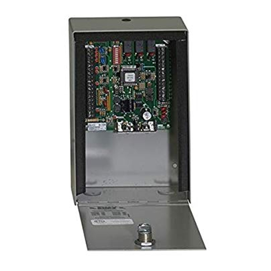
Single Housing • P/N 2351-080 provides a lockable, weather resistant housing for a single tracker board. Single Board Enclosure 4.875 3.625 .187 DIA 4 PL 5.75 .875 DIA 2 PL 3.75 DOORKING, INC., INGLEWOOD, CA 90301 Single Enclosure for 2351-010 Board... -
Page 23: Quad Housing
Quad Housing • P/N 2351-081 provides a lockable weather resistant housing for up to four (4) tracker boards. Includes terminal strips and four (4) convenience outlets for power transformers. FOUR BOARD ENCLOSURE FRONT SIDE 13.0 .875 DIA 2 PL .875 DIA 2 PL 1.125 DIA... - Page 24 Page 2351-065-G-12-07...
-
Page 25: Section 3 - Wiring Information
Controller main terminals 15-16-17 = System Relay 1. Controller main terminals 13-14 = System Relay 2. Relay 0 is used when system expands to 9 2351-010 boards or more, otherwise system relay 1 is used for main door/gate control. Relay 0 is not available on the 1818 or 1837 controller. -
Page 26: Tracker Boards 1-8 Detail Wiring For 40 And 50 Series Control Boards
• Do not use twisted pair wire with weigand output format. • Proper grounding is required! Ground wire should be a minimum 12 AWG. 40 and 50 Series Controller to 2351-010 Expansion Boards 1-8 Detail Wiring Elevator Control RS 232... -
Page 27: Tracker Boards 9-16 Detail Wiring For 40 Series Control Boards
2351-010 INPUT MAIN DR/GATE Belden 9931 or Equivalent. Shield runs continuous. Float the shield, do not connect shield to 2351-010 board common. Relay 0 1 2 3 Belden 9418 or Equivalent. If reader is lighted, use Belden 9931. 16 VAC Communication cable to additional boards is connected in parallel. -
Page 28: Tracker Boards 1-8 Detail Wiring For 30 Series Control Boards
Maximum wire run between Tracker boards 1-8 is 500 feet total. • Do not use twisted pair wire with weigand output format. • Proper grounding is required! Ground wire should be a minimum 12 AWG. 30 Series Controller to 2351-010 Expansion Boards 1-8 Detail Wiring RS 232 Elevator Connection... -
Page 29: Tracker Boards 9-16 Detail Wiring For 30 Series Control Boards
Maximum wire run between Tracker boards 9-16 is 500 feet total. • Do not use twisted pair wire with weigand output format. • Proper grounding is required! Ground wire should be a minimum 12 AWG 30 Series Controller to 2351-010 Expansion Boards 1-16 Detail Wiring LOCK LOCK RS 232... -
Page 30: Block Diagram Single Door Control
Ground circuit board. Use 12 GA. Wire. Gate operator inputs are for operator data only. Gate operator input 1 from DKS slide, swing or overhead operators only. Gate operator input 2 from DKS barrier gate operators only. Local alarm and alarm system outputs are dry relay contacts. -
Page 31: Door Control Wiring
Red = 12 VDC Power If card reader is lighted, separate light power must be provided. NOTE: Wiring to controller/other tracker boards is not shown. DOORKING, INC., INGLEWOOD, CA 90301 Title: Detail Wiring - 2351-010 Expansion Board Door Control Date: 3/03 Dwg. No. -
Page 32: Gate Operator Data
TERM 4 5 6 Belden 9931 or Equivalent. Wiring indicated by dashed (- - -) lines is required only if the 2351-010 board is to command open the vehicular gate when a valid access code has been received . NOTE:... - Page 33 MAIN TERM Belden 9931 or Equivalent. Wiring indicated by dashed (- - -) lines is required only if the 2351-010 board is to command open the vehicular gate when a valid access code has been received . NOTE: Wiring show is for the connection of DKS vehicular gate operators only to the 2351-010 board to record gate operator data.
-
Page 34: General Wiring Information
(10) feet away from the gate and gate operator, or in such a way that a person cannot operate the access control device and touch the gate or gate operator at the same time. Page 2351-065-G-12-07... -
Page 35: Section 4 - Trouble Shooting
A backup battery should be connected to the tracker board as described in section 4.2. LED Identification The illustration below identifies the terminals and LEDs that are useful for trouble shooting purposes. 2351-010 Board LED Identification LEDs Gate 1 Data Input Gate 1 Data Output... -
Page 36: Weigand Device Data
Page 2351-065-G-12-07... -
Page 37: Gate Operator Data
When this happens, the weigand output LED will light, and the tracker board busy LED will light. After the data has been sent, these LED's will go off. The tracker board cannot receive any data if the busy LED (P2-10) is lighted. 2351-065-G-12-07 Page... -
Page 38: Gate Operator Event Report
Gate Operator Event (transaction) Reports The tracker interface board sends the following gate operator data to the DKS access control system. This data is stored in a separate file in the access system and can be viewed by clicking the GATE button on the transaction report screen in the DoorKing Remote Account Manager for Windows software. - Page 39 2351-065-G-12-07 Page...
Need help?
Do you have a question about the 2351 and is the answer not in the manual?
Questions and answers