
Related Manuals for Frequency Devices CPCI32FF

Summary of Contents for Frequency Devices CPCI32FF
- Page 1 Model CPCI32FF 32 Channel CPCI Board User Manual 1784 Chessie Lane, Ottawa, Illinois 61350 • Tel: 800/252-7074, 815/434-7800 • FAX:815/434-8176 e-mail: sales@freqdev.com • Web Address: http://www.freqdev.com...
-
Page 2: Table Of Contents
8.0 Repair APPENDICES A. CPCI32FF Specifications Figures 1. CPCI32FF Top View 2. Jumper Configuration 3. Block Diagram of a Typical Channel 4. Front Panel We hope the information given here will be helpful. The information is based on data and our best knowledge, and we consider the information to be true and accurate. -
Page 3: Unpacking And Inspection
If the board appears to be damaged in any way, notify the shipping carrier. 3.0 - Hardware Configuration Once the CPCI32FF has been removed from its anti-static bag and inspected for damage, you are ready to configure the board. -
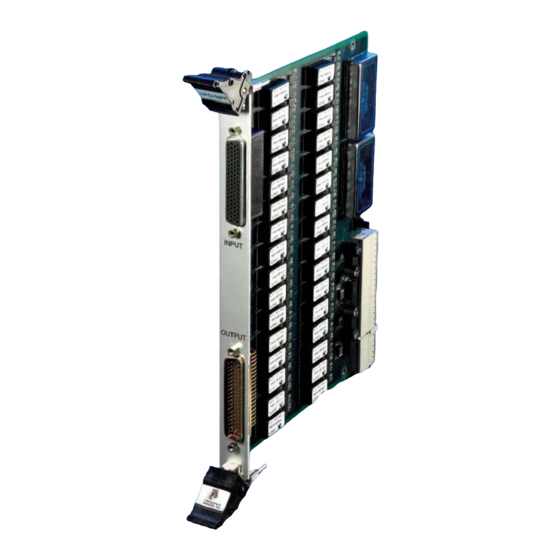
Page 4: Cpci32Ff Top View
Model CPCI32FF 32 Channel CPCI Board User Manual See Figure 2 for J1 Jumper detail Figure 1 CPCI32FF Top View 1784 Chessie Lane, Ottawa, Illinois 61350 • Tel: 800/252-7074, 815/434-7800 • FAX:815/434-8176 e-mail: sales@freqdev.com • Web Address: http://www.freqdev.com... -
Page 5: Block Diagram Of A Typical Channel
32 Channel CPCI Board User Manual The only user configuration on the CPCI32FF is Jumper J1 (Figure 2), to select the ground reference to the analog circuitry. Jumper J1 allows the analog common of the channel path to float, be referenced to the front panel chassis ground, or be connected to the CPCI back plane power supply return. -
Page 6: Board Installation
WHEN HANDING THE BOARD. Frequency Devices' Model CPCI32FF mechanically conforms to the single width 6U CPCI form factor. The CPCI32FF may be installed in any available CPCI slot except Slot 0. The board does not use CPCI interrupts or bus mastering capabilities. - Page 7 Model CPCI32FF 32 Channel CPCI Board User Manual CPCI32FF 78 pin female INPUT OUTPUT 78 pin male Figure 4 CPCI32FF Front Panel 1784 Chessie Lane, Ottawa, Illinois 61350 • Tel: 800/252-7074, 815/434-7800 • FAX:815/434-8176 e-mail: sales@freqdev.com • Web Address: http://www.freqdev.com...
-
Page 8: Input And Output Connector Configurations
Model CPCI32FF 32 Channel CPCI Board User Manual 5.2. - Input and Output Connector Configurations The input connector on the board is a female 78 pin high-density D-sub connector. The output connector is a male 78 pin high-density D-sub connector. Input and output connectors have the same pin out. -
Page 9: Troubleshooting And Technical Support
Ottawa, IL 61350 7.0 – Warranty Information The CPCI32FF is warranted against defects in material and workmanship for a period of one (1) year from the date of shipment. During the warranty period, Frequency Devices, Inc. will, at its option, repair or replace products that prove to be defective. - Page 10 32 Channel CPCI Board User Manual 8.0 - Repair Frequency Devices, Inc. maintains a repair facility at its factory in Ottawa, Illinois that is available for both in-warranty and non-warranty repairs. We suggest that you contact Frequency Devices at sales@freqdev.com for a Return Authorization (RA) number before taking steps to return equipment for repair.
- Page 11 Model CPCI32FF Specifications (Typical @ 25 o C and rated Power Input) APPENDIX A Analog Input 1. Impedance 1 GΩ / 47pF ±10V pk. linear 2. Input Range ±40V 3. Maximum Input 4. Common Mode Rejection 75 dB min. @ 60 Hz.
Need help?
Do you have a question about the CPCI32FF and is the answer not in the manual?
Questions and answers