
Related Manuals for Rotronic HS5

Summary of Contents for Rotronic HS5
- Page 1 Rotronic E-M-HS5-V1_00 Bassersdorf, Switzerland Instruction Manual HS5 – Hygrostat / Thermostat Instruction Manual Page 1 of 40 Hygrostat/Thermostat Instruction Manual © 2016; Rotronic AG E-M-HS5-V1_00...
-
Page 2: Table Of Contents
2 of 40 Contents Contents ................................2 Short Description of the Product ....................... 4 Delivery Package ..........................5 Main Features of the HS5 Transmitter ....................6 Technical Drawing ..........................7 General Description ..........................8 Power Supply ........................... 8 Connections............................9 HC2 Connection .......................... - Page 3 Rotronic E-M-HS5-V1_00 Bassersdorf, Switzerland Instruction Manual HS5 – Hygrostat / Thermostat Instruction Manual Page 3 of 40 Accessories ............................39 Service Cables ..........................39 Mounting Elements ......................... 39 Additional Documents ........................40 Document Versions ........................... 40 © 2016; Rotronic AG...
-
Page 4: Short Description Of The Product
4 of 40 Scope: This manual is valid for the HS5 transmitter series with firmware version V3.x. The low-order digit of the firmware version stands for minor changes, e.g. correction of errors, that do not influence the main functionality of the device. -
Page 5: Delivery Package
Rotronic E-M-HS5-V1_00 Bassersdorf, Switzerland Instruction Manual HS5 – Hygrostat / Thermostat Instruction Manual Page 5 of 40 1.1 Delivery Package Hygrostat / Thermostat Per order code (A HygroClip2 probe must be ordered separately) Factory adjustment certificate Short instruction manual Mounting screws and wall plugs ©... -
Page 6: Main Features Of The Hs5 Transmitter
Bassersdorf, Switzerland Instruction Manual HS5 – Hygrostat / Thermostat Instruction Manual Page 6 of 40 1.2 Main Features of the HS5 Transmitter • • Measures relative humidity and temperature • • All psychrometric calculations available • • Outstanding accuracy and repeatability •... -
Page 7: Technical Drawing
Manual Page 7 of 40 1.3 Technical Drawing The HS5 comes as wall-mounted unit in a normal ROTRONIC housing. The following drawings show the relevant overall dimensions in mm. Figure 1: Overall dimensions of the HS5 © 2016; Rotronic AG... -
Page 8: General Description
8 of 40 General Description 2.1 Power Supply The HS5 is only available as three-conductor version without galvanic isolation. For configuration purposes, the device can also be supplied with power via the service interface (Mini-USB port inside housing). 2.1.1 Power Supply / Current Consumption... -
Page 9: Connections
HS5 to an Ethernet LAN (LAN: Local Access Network). The MAC address (MAC: Media Access Control) of the HS5 is printed on the top side of the RJ45 socket enclosure. It can be used for unique identification of the device in a LAN. -
Page 10: Hc2 Connection
2.3 HC2 Connection The HS5 optionally comes with a HC2 connection socket. It can be used for all HC2 probes in the ROTRONIC portfolio. Alternatively, one pin of the socket can be used as analog current or voltage input. It must be established on ordering the device whether the pin can evaluate current or voltage signals;... - Page 11 2.4.1 Scale The scale can be changed at will with the ROTRONIC HW4 software in a range from -9,999 to +99,999. The limits of the sensor must, however, be observed. The devices have one of the following optional default settings on delivery:...
-
Page 12: Relays
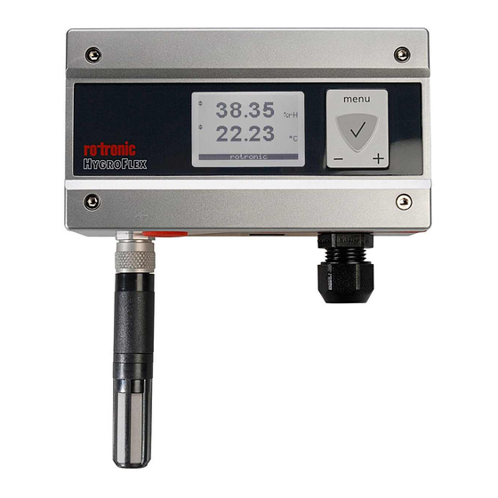
Bassersdorf, Switzerland Instruction Manual HS5 – Hygrostat / Thermostat Instruction Manual Page 12 of 40 2.5 Relays The HS5 provides a freely configurable internal isolated relay changeover contact. • Normally closed (NC) • Common (COM) • Normally open (NO) The relay can be controlled by freely configurable alarms. The following can also be set: •... - Page 13 Instruction Manual HS5 – Hygrostat / Thermostat Instruction Manual Page 13 of 40 The front side of the HS5 has a three-line black-and-white LCD in the middle and a membrane keypad on the right. Keys Menu (open and close operating menu) √...
-
Page 14: Hw4 Software Compatibility
14 of 40 2.7.2 Decimals The HS5 adjusts the number of decimal places automatically on the basis of the current measured value. The display therefore always shows the measured value clearly with the corresponding number of significant decimals. 2.8 HW4 Software Compatibility HS5 hygrostat / thermostat transmitters are fully integrated in the HW4 software. -
Page 15: Mechanical Installation
Mechanical Installation 3.1 General The HS5 can be mounted on a wall or on a DIN top-hat rail. The device is not sensitive to position. However, for exact measurement, the device must not move and must not be exposed to vibrations. -
Page 16: Mounting
The HS5 can optionally be ordered with an E2 socket. This interface and its possible uses are described below. 3.4.1 Use of HC2 Probe The HS5 can optionally be set up for a HC2 probe. After connection of a HC2 probe, it is possible to measure and display three parameters: •... - Page 17 Remark: The HS5 does not contain a power supply for an analog third-party probe. If adequate, the power supply for the HC2 probe can be used via the pins V+ and GND (see Abbildung 5). When using an analog probe, be sure to define both the voltage signal range and the measurement range of the probe.
-
Page 18: Electrical Installation
Cable Grip and Cable Specifications The HS5 comes with a sealing M16 cable grip with screw cable gland. The M16 cable grip only offers effective sealing if cables with external diameters of 6 to 7 mm (0.236 to 0.275 inch) with connection wires per 18 AWG are used. - Page 19 Rotronic E-M-HS5-V1_00 Bassersdorf, Switzerland Instruction Manual HS5 – Hygrostat / Thermostat Instruction Manual Page 19 of 40 • Bus signals such as RS-485 • Data signals for PCs, printers, etc. • Shielded analog inputs • in common bundles or channels / conduits Unshielded DC voltage (<= 60 V)
-
Page 20: Wiring
This section describes the wiring of the device with connection possibilities. 4.2.1 Electrical Diagrams The HS5 is wired with a four-pin connection cable for transmission of the electrical power and measured values. The maximum permissible cable length depends on the voltage drop caused by the flow of current to the devices connected to the HS5 outputs. - Page 21 Terminal K2-3 (protective ground) is connected ex works with GND due to the closed solder jumper B5. If this is not wanted, open solder jumper B5. Warning: Before connecting the HS5 to an active Ethernet network, make sure it is configured correctly for IP communication. Otherwise conflicts could disturb communication in the network. © 2016; Rotronic AG...
-
Page 22: Operation
ROTRONIC HW4 software are asked to consult ROTRONIC. The Ethernet interface of the HS5 can be used best together with a PC with installed HW4 software (version 3.2 or later). Users may in principle access the measured data of the HS5 with any communication software. This is described in detail in the document E-M-AC3000-CP. - Page 23 Rotronic E-M-HS5-V1_00 Bassersdorf, Switzerland Instruction Manual HS5 – Hygrostat / Thermostat Instruction Manual Page 23 of 40 5.2.1 Scaling of the Analog Input The analog input can be scaled within the range 0…3.2 V / 0…25 mA. If, for example, only 1...2.5 V are to be shown in the display due to the application or a connected third-party probe, the analog input must be scaled accordingly.
- Page 24 Rotronic E-M-HS5-V1_00 Bassersdorf, Switzerland Instruction Manual HS5 – Hygrostat / Thermostat Instruction Manual Page 24 of 40 5.2.2 Scaling of the Analog Outputs The display range (Scale = ScaleHi - ScaleLo) of the Display-Value can be selected freely within the complete...
-
Page 25: Display And Keys
Display and Keys The HS5 is configured ex works such that it can be used and managed as hygrostat or thermostat within broad limits without a service cable and LAN integration. It is integrated in an IP network (LAN) with a PC running the HW4 software via the RJ45 socket. -
Page 26: Submenus
Page 26 of 40 Submenus The submenus enable fine parameterization of the HS5. To open a submenu, move to the menu name in the √ main menu with the + or - key and then press the key. The further settings in the various submenus are described below. - Page 27 An alarm is emitted when the bottom alarm threshold is not reached or the top alarm threshold is passed. These are relative humidity values (%rh) when the HS5 is being used as hygrostat and temperature values (°C, K) when it is being used as thermostat. When an alarm condition occurs, the relay is energized immediately if it has been enabled.
- Page 28 Probe Information The HC2 probe (HygroClip 2) is an independent measuring instrument. Detailed information on it is to be found in the corresponding document (to be found at www.rotronic.com). The first five lines contain information only and cannot be changed.
-
Page 29: Relay
Rotronic E-M-HS5-V1_00 Bassersdorf, Switzerland Instruction Manual HS5 – Hygrostat / Thermostat Instruction Manual Page 29 of 40 5.5.6 Temperature Adjust RefValue: Enter the reference value of a temperature standard and confirm with <Acquire>. (One-point adjustment, only one reference value can be entered.) -
Page 30: Maintenance
Rotronic E-M-HS5-V1_00 Bassersdorf, Switzerland Instruction Manual HS5 – Hygrostat / Thermostat Instruction Manual Page 30 of 40 Maintenance 6.1 Service Cable Suitable service cables • AC3006: requires additional power supply to the device • AC3009: supplies the device directly with 5 VDC 6.2 Service Port... -
Page 31: Device Calibration And Adjustment Procedure
Rotronic E-M-HS5-V1_00 Bassersdorf, Switzerland Instruction Manual HS5 – Hygrostat / Thermostat Instruction Manual Page 31 of 40 6.3 Device Calibration and Adjustment Procedure The electronics are very stable and require no maintenance. They do not normally need to be changed or recalibrated after factory calibration. - Page 32 The calibration point is deleted automatically from the probe memory after adjustment. • Since the HS5 does not have a real-time clock, the date of the adjustment is not written in the probe. If it is important to record the adjustment date, use the HW4 software to adjust the probe.
- Page 33 Page 33 of 40 Humidity Adjustment The keypad of the HS5 enables multi-point adjustment of the humidity. The effect of a humidity adjustment differs in dependence on the number of calibration points entered into the probe memory before adjustment: •...
-
Page 34: Validation Of Analog Output Signals
The text line Delete can be used to delete all calibration points before probe adjustment. • Since the HS5 does not have a real-time clock, the date of the adjustment is not written in the probe. If it is important to record the adjustment date, use the HW4 software to adjust the probe. -
Page 35: Technical Data
Rotronic E-M-HS5-V1_00 Bassersdorf, Switzerland Instruction Manual HS5 – Hygrostat / Thermostat Instruction Manual Page 35 of 40 Technical Data General Hygrostat / Thermostat transmitter with analog output signals and optional Device type Ethernet interface Circuit type 3-wire circuit Mounting types... - Page 36 Rotronic E-M-HS5-V1_00 Bassersdorf, Switzerland Instruction Manual HS5 – Hygrostat / Thermostat Instruction Manual Page 36 of 40 Dew point (Dp) above and below freezing point Frost point (Fp) below freezing point and dew point above freezing point Wet bulb temperature (Tw)
- Page 37 Rotronic E-M-HS5-V1_00 Bassersdorf, Switzerland Instruction Manual HS5 – Hygrostat / Thermostat Instruction Manual Page 37 of 40 Configurable Analog Outputs Output 1 Can be assigned to every parameter Default parameter Relative humidity / Temperature Default range Per order code Output 2...
- Page 38 Rotronic E-M-HS5-V1_00 Bassersdorf, Switzerland Instruction Manual HS5 – Hygrostat / Thermostat Instruction Manual Page 38 of 40 General Specifications Optional display LC, resolution 1 or 2 decimals, backlight, trend and alarm indicators Housing material IP65 (without Ethernet interface) Housing protection grade...
-
Page 39: Accessories
Rotronic E-M-HS5-V1_00 Bassersdorf, Switzerland Instruction Manual HS5 – Hygrostat / Thermostat Instruction Manual Page 39 of 40 Accessories 9.1 Service Cables Order Code Description AC3006 Service cable, USB to UART Service cable, USB to UART with integrated AC3009 power supply... -
Page 40: Additional Documents
Rotronic E-M-HS5-V1_00 Bassersdorf, Switzerland Instruction Manual HS5 – Hygrostat / Thermostat Instruction Manual 40 of 40 Page Additional Documents Document Name Contents E-M-HC2 Probes HC2 manual E-M-HW4v3-Main HW4 software main manual E-M-TCPIP-Conf Manual for Ethernet configuration of ROTRONIC instruments E-M-AC3000-CP...