Table of Contents
Advertisement
Quick Links
Advertisement
Table of Contents

Subscribe to Our Youtube Channel
Related Manuals for hager HIC4 A Series

Summary of Contents for hager HIC4 A Series
- Page 1 z Automatic Transfer Switching Equipment Instruction manual HIC4xxA 6LE007621A...
- Page 2 Index 1. General Safety Instructions 2. Introduction 3. HIC4xxA versions 3.1. Product presentation 3.2. Specifications and advantages 3.3. Supply types 4. Optional accessories 5. Technical data 6. Environmental conditions 7. Product installation 7.1. Changing the padlocking configuration 7.2. Recommanded orientation 7.3.
- Page 3 10. Connection of control/command circuits 10.1. Terminal connectors designation 10.2. Auxiliary contact operating schedule 11. Operation 11.1. Presentation of the product interface 11.1.1. Product interface 11.1.2. Reset 11.2. Manual mode 11.3. Manual switching 11.4. Padlocking 11.5. Programming 11.5.1. Single phase version 11.5.2.
-
Page 4: General Safety Instructions
One must also refer to and respect markings on the product prior to installation and commissioning for values and limits specific to that product. • Using the product outside the intended scope, outside Hager recommendations or outside the The information provided in this instruction manual is specified ratings and limits can cause personal injury and/or damage to equipment. - Page 5 2. Introduction HIC4xxA “Automatic Transfer Switching Equipment” (ATSE) is designed for use in power systems for the safe transfer of a load supply between a normal and an alternate source. The changeover is done in open transition and with minimum supply interruption during transfer ensuring full compliance with IEC 60947-6-1, GB 14048-11 and other international TSE standards as listed.
-
Page 6: Selection Guide
Selection guide Seven ratings: 20A/40A/63A/80A/100A/125A/160A HIC4xxA Applications Normal / Backup with built-in automatic controller • Stable positions • Functions Power supply Integrated • Operation Backup manual operation of the 3 positions • Automatic control of positions I, 0 and II •... -
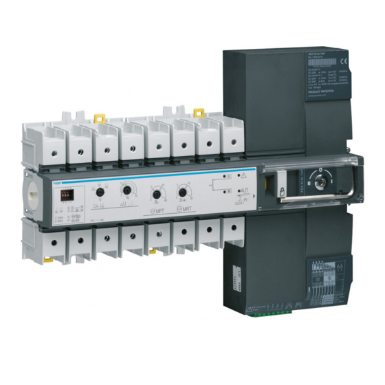
Page 7: Product Presentation
3. HIC4xxA versions The HIC4xxA is available as 4P with the possibility of being used on virtually any automatic open transition type of application. Measurement accuracy: Frequency: 1 % - Voltage: 1 % 3.1. Product presentation This quick-acting transfer switch incorporates: 1. 2 mechanically interlocked switches. 2. -
Page 8: Optional Accessories
4. Optional accessories Auxiliary Each product can take up to 2 auxiliary contact blocks. Ref. : HZI300 contacts Each accessory integrates 1 NOC auxiliary contact (for each position I, O and II) HZI300. Characteristics: 5A 250 VAC / 5A 30 VDC maximum. Bridging bars To provide a common point on the outgoing side of the Three phase product:... -
Page 9: Technical Data
5. Technical data Ratings 20 A 40 A 63 A 80 A 100 A 125 A 160 A Frequencies 50/60 Hz 50/60 Hz 50/60 Hz 50/60 Hz 50/60 Hz 50/60 Hz 50/60 Hz Thermal current Ith at 40 °C (A) Thermal current Ith at 50 °C (A) 110* Thermal current Ith at 60 °C (A) 100*... -
Page 10: Environmental Conditions
6. Environmental conditions Humidity • 80 % humidity without condensation at 55 °C • 95 % humidity without condensation at 40 °C Temperature • -20 +40 °C without de-rating • 40 °C < t ≤ 70 °C with de-rating (see Technical Characteristics) Altitude •... -
Page 11: Product Installation
7. Product installation Prior to installation of the product ensure that the padlocking setting screw (located at the back of the product) is configured as per your requirements. For locking in Positions I, II and 0, refer to the following procedure 7.1. -
Page 12: Din Rail Mounted
7.5. DIN rail mounted Tighten to avoid movement on the DIN rail. DIN RAIL IEC 60715 Posidriv PZ1 1 Nm 8. Installation of optional accessories 8.1. Auxilliary contacts Ref. HZI300 To fit an AC, the switch must first be put in the 0 position. An auxiliary contact module comprises: one NO/NC changeover contact for each position (I-0-II). -
Page 13: Terminal Shrouds
8.3. Bridging bars 4P Ratings ≤ 125A: ref. HZI400; 160A : ref. HZI401 LOAD Source I Source II Hexagonal Metric Load side 10 to 70 mm Allen size 4 # 8 to # 00 AWG 10 to 70 mm bridging bar. 5.0 Nm 6 to 70 mm # 8 to # 00 AWG... - Page 14 9. Connection of the power circuits Hexagonal Metric Allen size 4 5.0 Nm 10 to 70 mm² 15 mm Source supply side It is essential to tighten all used terminals, with cables and/or bridging bars, before use. 9.1. Ratings / cross-sections table of correspondence 20 A 40 A 63 A...
-
Page 15: Network Configurations
9.3. Network configurations 9.3.1. 230/400 VAC network configurations Load Type of Position of Terminal Terminal Terminal Terminal network the first dip switch 250VAC 5A AC1 30VDC 5A DC1 1P - Position B 1BL - Single 12 14 11 (dip switch phase down) 4NBL -... - Page 16 9.3.3. Three phase without neutral network For three-phase networks without neutral (3NBL) 400 VAC, a neutral must be recreated to allow the HIC4xxA to operate at 230 VAC. To recreate the neutral, we recommend the use of quantity 2x 400 VA auto-transformers connected as shown below.
- Page 17 9.3.5. Procedure for the configuration and storage of the neutral position 230/400 VAC network configurations without neutral conductors. Load Step 1 It is first necessary to connect the HIC4xxA in three-phase + neutral (4NBL) to allow configuration of the neutral position (neutral position is detected at the first power-up).
- Page 18 10. Connection of control/command circuits Switch to manual mode before connecting the product. (Front Auto/Manu cover open). The product is delivered in the 0 position. Load side PUSH-IN solid 0,5 to 2,5 mm² stranded 0,5 to 1,5 mm² 10 mm 5 A AC1 250 Vac 250VAC 5A AC1...
- Page 19 10.1. Terminal connectors designation Status Recommended Output Type Terminal no. Application of the Description connection cross- characteristics contact section Inputs I1: 207 / 208 Network-Network With priority Without priority Dry potential free contact Network-Genset Automatic retransfer Manual retransfer I2: 207 / 209 Network-Network Source priority I Source priority II...
-
Page 20: Operation
10.2. Auxiliary contact operating schedule Position I Position I Position 0 Position 0 Position II Position II C.A. Position I C.A. Position I 11-14 Closed 11-12 Open C.A. Position 0 01-04 Closed C.A. Position 0 01-02 Open C.A. Position II C.A. - Page 21 11.1.2. Reset Operating fault reset Open and re-close the AUT/MAN cover 11.2. Manual mode To access manual mode, open the Aut/Man cover. Once manual mode is active (cover open) it is possible: • To lock the changeover switch. • To access the DIP switches programmation. •...
-
Page 22: Automatic Operation
Manual Retransfer 6 mm 01 04 02 Network / Network Source priority I Dry potential free Source priority II contact 0.5 to 2.5 mm Network / Genset Stop the test on load Test on load Network / Network AUTO mode or Network / Genset Automatic mode inhibition... - Page 23 250Vac 5A AC1 30Vdc 5A DC1 0.5 to 2.5 mm 11.5.2. Three phase version Use 20 mm screws for 1 module The LED signalling and operation is only active when the product supply is available. Use 35 mm screws for 2 modules To set the dip switches, it is necessary to open the Auto/Manual cover.
-
Page 24: Automatic Mode
11.6. Sealable configuration cover Configuration settings may be protected by means of a sealable cover. Refer to section «4. Optional accessories», page 18. 11.7. Automatic mode Close the cover to enter automatic mode. Make sure that the changeover switch is in automatic mode (AUT LED lit). - Page 25 11.9. Manual & Automatic Mode / Mains restoration conditions • Automatic mode returns to active 2 seconds after switching from manual to automatic mode. • Source I and source II voltages and frequencies are checked to define the changeover switch’s new stable status.
- Page 26 • Network - Genset application • Source 1 available • Product in position I • Contact 207/208 open • Contact 207/209 open Loss of source 1 Return of source 1 End of FT? Genset start order Genset available End of 5s timer + genset still available? Transfer...
- Page 27 11.9.2. Mode 2a: Controlled retransfer Network - genset application • Contact 207 / 208 closed => Manuel retransfer 207 209 TEST 5 sec. 5 sec. 207 208 4 min. 5 sec. TEST 5 sec. 207 208 207 209 Transfer Product in Source Source Timer is counting...
- Page 28 • Network - Genset application • Source 1 available • Product in position I • Contact 207/208 closed • Contact 207/209 open Loss of source 1 Return of End of FT? source 1 Genset start End of 5s timer? Genset always Transfer I ->...
- Page 29 11.9.3. Mode 2b: Controlled transfer Network - genset application • Contact 207 / 208 closed => Test on load • Configuration Network - Genset • Source 1 available • Product in position I • Contact 207/208 open or closed • Contact 207/209 open Closing of contact 207/209 End of 5s...
- Page 30 11.9.4. Mode 3: Network - Network application with priority Network - network application • Contact 207 / 208 open => functioning with priority. 207 209 TEST 5 sec. PRIORITY 5 sec. TEST PRIORITY 207 209 Transfer Product in Source Source Timer is counting NORMAL PRIORITY II...
- Page 31 • Network - Network application • Sources 1 and 2 available • Product in position I • Contact 207/208 open • Contact 207/209 open Closing of contact 207/209 Priority source 2 Loss of End of 5s timer? source 2 Return of source 2 Transfer End of RT?
- Page 32 11.9.5. Mode 4: Network - Network application without priority Network - Network application • Contact 207 / 208 closed => functioning without priority. 207 209 TEST 5 sec. 5 sec. TEST 207 209 Transfer Product in Source Source Timer is counting NORMAL PRIORITY II TEST...
- Page 33 • Network - Network application • Sources 1 and 2 available • Product in position I • Contact 207/208 closed • Contact 207/209 open Return of source 2 Impulsion of contact 207/209 Loss of End of 5s timer? source 2 Transfer I ->...
-
Page 34: Preventative Maintenance
12. Preventative maintenance It is recommended to operate the product at least once a year. I - O - II - O - I Note: Maintenance should be planned carefully and carried out by qualified and authorised personnel. Consideration of the critical level and application where the product is installed should form an essential and integral part of the maintenance plan. -
Page 35: Troubleshooting Guide
• Manual mode = cover open continues to operate Check that automatic operation has not been inhibited by an external order (terminals 207-210). Hager Electro S.A.S., Boulevard d'Europe, B.P. 3, 67215 OBERNAI CEDEX, France - www.hager.com Hager 01.21 - OCOM 140736 6LE007621A...
Need help?
Do you have a question about the HIC4 A Series and is the answer not in the manual?
Questions and answers