Advertisement
Service Literature
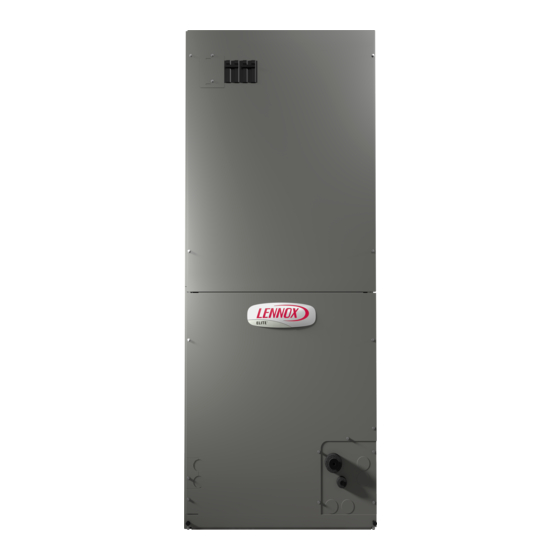
IT IS HIGHLY RECOMMENDED IF THE AIR HANDLER IS INSTALLED IN A
UNCONDITIONED SPACE THAT A CIRCUIT BREAKER COVER (ORDERED
SEPARATELY) IS USED. ORDER LENNOX CATALOG # 82W01.
CIRCUIT BREAKER
OPENING
WARNING
Improper installation, adjustment, alteration, service or
maintenance can cause personal injury, loss of life, or
damage to property.
Installation and service must be performed by a licensed
professional installer (or equivalent) or a service agency.
CAUTION
As with any mechanical equipment, contact with sharp
sheet metal edges can result in personal injury. Take care
while handling this equipment and wear gloves and pro
tective clothing.
Corp. 1701-L3
May 2017
®
Elite
Series CBA27UHE Units
CIRCUIT BREAKER
COVER
Page 1
Table of Contents
. . . . . . . . . . . . . . . . . . . . . .
. . . . . . . . . . . . . . . .
. . . . . . . . . . . . . . . . . . . . . .
. . . . . . . . . . . . . . . .
III Optional Electric Heat
. . . . . . . . . . . . . . . . . . . . . . .
. . . . . . . . . . . . . . . . . . .
. . . . . . . . . . . . . . . . . .
The Elite CBA27UHE units are high efficiency blower coils
featuring an all-aluminum coil. Several models are avail
able in sizes ranging from 1-1/2 through 5 tons (5.3 through
17.6 kW). The CBA27UHE is an upflow horizontal unit de
signed for HCFC-410A refrigerant. See unit installation in
structions for more detail. A kit is available for downflow ap
plications. CBA27UHE units come with a factory-installed
check / expansion valve for cooling or heat pump applica
tions.
CBA27UHE series units are designed to be matched with 14
SEER air conditioner or heat pump units. While these blower
coil units are designed to be primarily matched with these out
door units, they may be matched with other air conditioners or
heat pumps as noted in the rating information.
ECB29 electric heat, in several voltages and kW sizes, can be
field installed in the CBA27UHE cabinets.
Information contained in this manual is intended for use by ex
perienced HVAC service technicians only. All specifications are
subject to change. Procedures outlined in this manual are pre
sented as a recommendation only and do not supersede or re
place local or state codes.
IMPORTANT: Special procedures are required for clean
ing the aluminum coil in this unit. See page 29 in this manual
for information.
CBA27UHE
. . . . . .
Page 2
Page 4
Page 6
Page 7
Page 7
. . . . . . . . . . .
Page 9
Page 28
. .
Page 28
Page 29
Page 32
2017 Lennox Industries Inc.
Advertisement
Table of Contents

Subscribe to Our Youtube Channel
Related Manuals for Lennox Elite CBA27UHE Series


Summary of Contents for Lennox Elite CBA27UHE Series
-
Page 1: Table Of Contents
UNCONDITIONED SPACE THAT A CIRCUIT BREAKER COVER (ORDERED VII Wiring Diagrams and Sequence SEPARATELY) IS USED. ORDER LENNOX CATALOG # 82W01. of Operations .... -
Page 2: Specifications / Electrical Data
SPECIFICATIONS General Model Number CBA27UHE‐018 CBA27UHE‐024 CBA27UHE‐030 CBA27UHE‐036 Data Nominal tonnage Connections Suction (vapor) line (o.d.) - in. sweat Liquid line (o.d.) - in. sweat Condensate - in. fpt (2) 3/4 (2) 3/4 (2) 3/4 (2) 3/4 Net face area - ft. 4.44 4.44 Indoor... - Page 3 SPECIFICATIONS General Model Number CBA27UHE‐042 CBA27UHE‐048 CBA27UHE‐060 Data Nominal tonnage Connections Suction (vapor) line (o.d.) - in. sweat Liquid line (o.d.) - in. sweat Condensate - in. fpt (2) 3/4 (2) 3/4 (2) 3/4 Indoor Net face area - ft. 7.22 7.22 8.33...
-
Page 4: Blower Data
BLOWER DATA CBA27UHE−018 BLOWER PERFORMANCE External Air Volume and Motor Watts Static Tap 1 Tap 2 Tap 3 Tap 4 Tap 5 Pressure Watts Watts Watts Watts Watts in. w.g. CBA27UHE−024 BLOWER PERFORMANCE External Air Volume and Motor Watts Static Tap 1 Tap 2 Tap 3... - Page 5 BLOWER DATA CBA27UHE−042 BLOWER PERFORMANCE External Air Volume and Motor Watts Static Tap 1 Tap 2 Tap 3 Tap 4 Tap 5 Pressure Watts Watts Watts Watts Watts in. w.g. 1282 1346 1497 1489 1723 1143 1278 1475 1461 1690 1067 1233 1447...
-
Page 6: Parts Arrangement
CBA27UHE PARTS ARRANGEMENT ELECTRIC HEAT SECTION CONTROL BOX *BLOWER ACCESS PANEL BLOWER COMPARTMENT HORIZONTAL *COIL ACCESS DRAIN PAN PANEL COIL FILTER ACCESS EXPANSION VALVE PANEL (COMPLETE WITH SCREEN) FILTER FIGURE 1 Page 6... -
Page 7: I Application
II-UNIT COMPONENTS A-Control Box All major blower coil components must be matched ac cording to Lennox recommendations for the unit to be See figure 2 for CBA27UHE control box. Line voltage and covered under warranty. Refer to the Product Specifications electric heat connections are made in the control box. - Page 8 C-Transformer (T1) BLOWER ASSEMBLY CBA27UHE series units use a single line voltage to 24VAC transformer mounted in the control box. The transformer supplies power to the control circuits in the indoor and outdoor unit. Transformers are rated at 70VA. 208/240VAC single phase transformers use two primary volt age taps as shown in figure 3.
- Page 9 CBA27UHE units are equipped with an indoor blower motor CBA27UHE to ECB29 matchups and electrical ratings. that is permanent magnetic with constant torque. The motor B-Electric Heat Components has 5 signal level speed taps, all referenced to the same sig nal common.
- Page 10 Circuit Breaker (CB1, CB2, and CB3) TB2 then routed to the CB unit through J/P2 The terminal strip is located in the lower left corner of the electric heat (208/230 volt only) vestibule panel. Single-phase electric heat uses two-pole terminal strips; while three-phase electric heat uses three- Line voltage connections are made to circuit breakers pole terminal strips.
- Page 11 ECB29‐8, ‐8CB, 9CB, ‐10, ‐10CB 208/230 SINGLE-PHASE ELECTRIC HEAT VESTIBULE PARTS ARRANGEMENT FIGURE 6 Page 11...
- Page 12 ECB29‐12.5CB, ‐15CB 208/230 SINGLE PHASE ELECTRIC HEAT VESTIBULE PARTS ARRANGEMENT FIGURE 7 Page 12...
- Page 13 ECB29‐8, ‐10 208/230 THREE PHASE ECB29-15CB 208/230 THREE PHASE ELECTRIC HEAT VESTIBULE PARTS ARRANGEMENT FIGURE 8 Page 13...
- Page 14 ECB29‐20CB 208/230 SINGLE-PHASE ELECTRIC HEAT VESTIBULE PARTS ARRANGEMENT FIGURE 9 Page 14...
- Page 15 ECB29‐25CB, ‐30CB 208/230 SINGLE-PHASE ELECTRIC HEAT VESTIBULE PARTS ARRANGEMENT FIGURE 10 Page 15...
- Page 16 ECB29‐20CB, ‐25CB 208/230 THREE-PHASE ELECTRIC HEAT VESTIBULE PARTS ARRANGEMENT FIGURE 11 Page 16...
- Page 17 ELECTRIC HEAT DATA − CBA27UHE−018 Input Blower Motor Minimum Maximum Model Number Full Circuit Overcurrent Volts Btuh Stages Load Ampacity Protection Amps SINGLE PHASE 2.5 kW ECB29−2.5 ( 12L27) 6,400 4 lbs. Terminal Block 7,200 7,800 8,500 4 kW ECB29−4 ( 1 2L30) 10,250 4 lbs.
- Page 18 ELECTRIC HEAT DATA − CBA27UHE−024 Input Blower Motor Minimum Maximum Model Number Full Circuit Overcurrent Volts Btuh Stages Load Ampacity Protection Amps SINGLE PHASE 4 kW ECB29−4 ( 1 2L30) 10,250 4 lbs. Terminal Block 11,450 ECB29−4CB ( 1 2L45) 30A Circuit breaker 12,550 13,650...
- Page 19 ELECTRIC HEAT DATA − CBA27UHE−030 Minimum Maximum Single Point Blower Input Circuit Overcurrent Power Source Motor Ampacity Protection Model Number Full Minimum Maximum Stages Load Volts kW Btuh Ckt 1 Ckt 2 Ckt 1 Ckt 2 Circuit Overcurrent Amps Ampacity Protection SINGLE PHASE 4 kW...
- Page 20 ELECTRIC HEAT DATA − CBA27UHE−036 Minimum Maximum Single Point Blower Input Circuit Overcurrent Power Source Motor Ampacity Protection Model Number Full Minimum Maximum Stages Load Volts kW Btuh Ckt 1 Ckt 2 Ckt 1 Ckt 2 Circuit Overcurrent Amps Ampacity Protection SINGLE PHASE 4 kW...
- Page 21 ELECTRIC HEAT DATA − CBA27UHE−036 Minimum Maximum Single Point Blower Input Circuit Overcurrent Power Source Motor Ampacity Protection Model Number Full Minimum Maximum Stages Load Volts kW Btuh Ckt 1 Ckt 2 Ckt 1 Ckt 2 Circuit Overcurrent Amps Ampacity Protection THREE PHASE 8 kW...
- Page 22 ELECTRIC HEAT DATA − CBA27UHE−042 SINGLE PHASE Minimum Maximum Single Point Blower Circuit Overcurrent Power Source Motor Ampacity Protection Volts Btuh Model Number Full Input Input Input Minimum Maximum Stages Load Ckt 1 Ckt 2 Ckt 3 Ckt 1 Ckt 2 Ckt 3 Circuit Overcurrent Amps...
- Page 23 ELECTRIC HEAT DATA − CBA27UHE−042 THREE PHASE Minimum Maximum Single Point Blower Input Circuit Overcurrent Power Source Motor Ampacity Protection No. of Model Number Full Stages Minimum Maximum Load Volts kW Btuh Ckt 1 Ckt 2 Ckt 1 Ckt 2 Circuit Overcurrent Amps...
- Page 24 ELECTRIC HEAT DATA − CBA27UHE−048 SINGLE PHASE Minimum Maximum Single Point Blower Input Circuit Overcurrent Power Source Motor Ampacity Protection Model Number Full Minimum Maximum Stages Load Volts kW Btuh Ckt 1 Ckt 2 Ckt 3 Ckt 1 Ckt 2 Ckt 3 Circuit Overcurrent Amps...
- Page 25 ELECTRIC HEAT DATA − CBA27UHE−048 THREE PHASE Minimum Maximum Single Point Blower Input Circuit Overcurrent Power Source Motor Ampacity Protection No. of Model Number Full Stages Minimum Maximum Load Volts kW Btuh Ckt 1 Ckt 2 Ckt 1 Ckt 2 Circuit Overcurrent Amps...
- Page 26 ELECTRIC HEAT DATA − CBA27UHE−060 SINGLE PHASE Minimum Maximum Single Point Blower Input Circuit Overcurrent Power Source Motor Ampacity Protection Model Number Full Minimum Maximum Stages Load Volts kW Btuh Ckt 1 Ckt 2 Ckt 3 Ckt 1 Ckt 2 Ckt 3 Circuit Overcurrent Amps...
- Page 27 ELECTRIC HEAT DATA − CBA27UHE−060 THREE PHASE Minimum Maximum Single Point Blower Input Circuit Overcurrent Power Source Motor Ampacity Protection No. of Model Number Full Stages Minimum Maximum Load Volts kW Btuh Ckt 1 Ckt 2 Ckt 1 Ckt 2 Circuit Overcurrent Amps...
-
Page 28: Start Up
IV-START‐UP - OPERATION 3- In all cases, blower and entire unit will be off when the system switch is in OFF position. A-Preliminary and Seasonal Checks B-External Static Pressure 1- Measure tap locations as shown in figure 12. 1- Make sure the unit is installed in accordance with the installation instructions. -
Page 29: Maintenance
MOTOR (ECM) (B3) pressure (less than 50psi). If the coil cannot be cleaned using water alone, Lennox recommends use of a coil cleaner with a pH in the range of 5 to 9. The coil must be rinsed thoroughly after cleaning. - Page 30 The constant torque ECM (electronically commutated motor) (C) terminal from the control relay. The motor accepts a communicates with the air handler control via 24VAC inputs. It communication signal of 24VAC on these taps. Instead of is programmed to provide a constant level of torque (current / energizing a motor speed (winding) on a PSC motor for power) to the motor.
- Page 31 Checking 230VAC Voltage Input DRIP LOOP First check the high voltage to terminals (L) and (N). There should be 230VAC on these two terminals whenever there CONNECTOR is power to the system, regardless of a demand call. Apply BACK OF ORIENTATION (BETWEEN UNIT 4 AND 8 O'CLOCK)
-
Page 32: Wiring Diagrams And Sequence Of Operations
VII-WIRING DIAGRAMS AND SEQUENCE OF OPERATIONS A- CBA27UHE Units 208/230V/460V SINGLE PHASE - SEQUENCE OF OPERATION 1- Line voltage is routed to transformer T1 and blower SINGLE-STAGE COOLING (Y1 to Y2 jumper in place) motor B3. 6- When there is a call for cooling, Y2 of the thermostat ener gizes blower on cooling speed. - Page 33 460V - Single Phase Page 33...
- Page 34 B-ECB29‐2.5, -4, ‐5, -6, 4CB, 5CB, 6CB - 208/230V SINGLE PHASE - SEQUENCE OF OPERATION 1- When there is a call for heat, W1 of the thermostat ener 3- Assuming the N.C. primary (S15) and secondary (S20) gizes the electric heat relay K35 with 24VAC. limit switches are closed, electric heat element HE1 is en...
- Page 35 C-ECB29‐8, 8CB 208/230V SINGLE PHASE - SEQUENCE OF OPERATION 1- When there is a call for heat, W1 of the thermostat ener 3- When K32‐2 and K32-3 close, assuming N.C. prima gizes the electric heat relays K32 and K33 with 24VAC. ry (S15) and the secondary (S20) limit switches are closed, electric heat element HE1 is energized.
- Page 36 D-ECB29‐9CB, 10, 10CB - 208/230V SINGLE PHASE - SEQUENCE OF OPERATION FIRST STAGE HEAT SECOND STAGE HEAT (remove jumper between W2 and R) 1- When there is a call for heat, W1 of the thermostat ener 4- When K33‐1 closes, the unit is ready for a second stage gizes the electric heat relays K32 and K33 with 24VAC.
- Page 37 E-ECB29‐12.5CB, ‐15CB - 208/230V SINGLE PHASE - SEQUENCE OF OPERATION FIRST STAGE HEAT SECOND STAGE HEAT (remove jumper between W2 and R) 1- When there is a call for heat, W1 of the thermostat ener 4- When K33‐1 closes, the unit is ready for a second stage gizes electric heat relays K32 and K33 with 24VAC.
- Page 38 F-ECB29‐20CB - 208/230V SINGLE PHASE - SEQUENCE OF OPERATION FIRST STAGE HEAT SECOND STAGE HEAT (remove jumper between W2 and R) 1- When there is a call for heat, W1 of the thermostat energizes the electric heat relays. 5- W2 of the thermostat sends a second stage heat de 2- When K32‐1 closes, the blower is energized on heat...
- Page 39 G-ECB29‐25CB - 208/230V SINGLE PHASE - SEQUENCE OF OPERATION FIRST STAGE HEAT 6- When K33‐2, K33-3, K117-1 and K117-2 close, assuming 1- When there is a call for heat, W1 of the thermostat ener primary (S15) and secondary (S20) limit switches are gizes the electric heat relays K32 and K34 with 24VAC.
- Page 40 H-ECB29 ‐8, ‐10 - 208/230V THREE PHASE - SEQUENCE OF OPERATION 1- When there is a call for heat, W1 of the thermostat 3- When K1 contactor closes, assuming the N.C. primary energizes the electric heat contactor K1. (S15) and secondary (S20) limit switches are closed, electric heat elements HE1, HE2, and HE3 are ener...
- Page 41 I-ECB29 ‐15CB - 208/230V THREE PHASE - SEQUENCE OF OPERATION 1- When there is a call for heat, W1 of the thermostat 3- When K1 contactor closes, assuming the N.C. primary energizes the electric heat contactor K1. (S15) and secondary (S20) limit switches are closed, electric heat elements HE1, HE2, and HE3 are ener...
- Page 42 J-ECB29‐20CB, ‐25CB - 208/230V THREE PHASE - SEQUENCE OF OPERATION FIRST STAGE HEAT SECOND STAGE HEAT (remove jumper between W2 and R) 1- When there is a call for heat, W1 of the thermostat ener 4- W2 of the thermostat sends a second stage heat de gizes the electric heat contactor K1 with 24VAC.
- Page 43 K-ECB29‐10, -15, -20 and -25CB - 460V THREE PHASE - SEQUENCE OF OPERATION FIRST STAGE HEAT SECOND STAGE HEAT (remove jumper between W2 and R) 1- When there is a call for heat, W1 of the thermostat 5- When K34‐2 closes, the unit is ready for a second stage energizes the electric heat relays K32 and K34 with heat demand.
- Page 44 L-CBA27UHE with DEHUMIDIFICATION RELAY K183 Operation Sequence Y1 cooling demand from the room thermostat with no dehumidification demand—24 volts passes to the Y1 ter 1-. If there is no dehumidification demand when 24 volts is minal on the coil blower. The Y1 demand will be isolated applied to the system, the thermostat will send 24 volts from the cooling tap speed on the indoor blower motor by to the K183 dehumidification relay coil.
- Page 45 CONNECT FOR 0.50 - 0.80 IN.W.G. ONLY; OTHERWISE, NOT USED DISCONNECT FROM Y2 Y1-Y2 JUMPER IN FOR CONNECT FOR 0.50 - 0.80 SINGLE-STAGE; IN.W.G., TWO-STAGE ONLY; REMOVED FOR OTHERWISE, NOT USED TWO-STAGE 0.50 - 0.80 IN.W.G. WHT - BRN 0.10 - 0.49 IN.W.G. WHT - WHT (PINS 4,8,12...
Need help?
Do you have a question about the Elite CBA27UHE Series and is the answer not in the manual?
Questions and answers