
Summary of Contents for ZERA TK326
- Page 1 OPERATION MANUAL Photo electric scanning head TK326 Keep for future use. TK326_MAN_EXT_GB_V102...
-
Page 2: Table Of Contents
2.3. Views of the TK326 ....................7 2.3.1. Front view of the TK326 ..................7 2.3.2. Rear view of the TK326 ................... 7 2.4 Technical data of TK326 ..................... 8 2.5 Using the TK326 with holding arrangement .............. 10 3. Service..........................12 TK326_MAN_EXT_GB_V102... -
Page 3: Safety Instructions
Scanning Head TK326 1. Safety Instructions The scanning head TK326 is developed only for scanning of rotor marks and LED’s of electronic meters. It is not allowed to modify the TK326 in any way. Only electrically skilled person (older than 18 years) having relevant education and experience which enable him/her to perceive risks and to avoid hazard/damage which electricity can create, are allowed to operate the equipment. -
Page 4: Important User Considerations
Scanning Head TK326 1.1. Important user considerations 1.1.1. Danger references In this manual the red box with black text is used to warn the operator that ignoring the message or action can cause hazard and/or damage to operator or property or test tools. -
Page 5: General Description
The scanning head TK326 is developed to scan rotor marks and LED’s of electronic meters. If the TK326 is used to scan rotor marks, pulsed LED’s light up the rotor disk. So the reflected light is pulsed as well and can be detected independent of the background light. The scanning heads TK326 can detect every single switching edge of a pulse and allows the automatic starting- and no load-test on ZERA test systems. -
Page 6: Scanning Of Led's
The switch on the rear side must be in the lower position („LED“ see chapter 2.3.2.). The potentiometer of the TK326 has no influence on scanning. The scanning head is positioned in front of the diode to be scanned in approx. 35 mm distance. The diode on the rear of the scanning head flashes in time with the pulse transmission. -
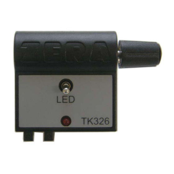
Page 7: Views Of The Tk326
Scanning Head TK326 2.3. Views of the TK326 2.3.1. Front view of the TK326 Serial-No. Part-No. 2.3.2. Rear view of the TK326 Potentiometer Switch Interface Pulse diode TK326_MAN_EXT_GB_V102... -
Page 8: Technical Data Of Tk326
Scanning Head TK326 2.4 Technical data of TK326 12 V ± 2 V DC Operating voltage: Current input: approx. 60 mA Output: 12 V / max. 50 mA Temperature range: 0 ... + 70° C Connector: RJ10 4-pole Pin 1... - Page 9 Scanning Head TK326 Scanning of LED’s : Wavelength: 450 ... 950 nm Distance to meter LED: 25 ... 50 mm Pulse data: max. frequency 1000 Hz max. rising time 20 µs min. pulse width 100 µs max. falling time 20 µs min.
-
Page 10: Using The Tk326 With Holding Arrangement
Scanning Head TK326 2.5 Using the TK326 with holding arrangement Examples for horizontal and vertical fixing at the meter LED-Scanning Holding arrangement for TK326 (standard) TK326 Holding arrangement for TK326 (optional) up to max. 220 mm TK326_MAN_EXT_GB_V102... - Page 11 Scanning Head TK326 Scanning of rotor marks Scanning of rotor marks Scanning of rotor marks (sideways) at electrical meters with bell jar Detail see right picture Holding arrangement Fixing of the holding arrangement TK326 with tension belt Tension belt TK326_MAN_EXT_GB_V102...
-
Page 12: Service
Scanning Head TK326 3. Service If you have technical questions, please contact our service department along with the following information: serial-number of the scanning head (position see chapter 2.3.1.) commissioning number detailed description of the problem TK326_MAN_EXT_GB_V102...
Need help?
Do you have a question about the TK326 and is the answer not in the manual?
Questions and answers