
Related Manuals for Tattile F01750

Summary of Contents for Tattile F01750
- Page 1 BASIC Automatic Number Plate Recognition Tattile S.r.l. Via G. Donizetti, 1 25030 Mairano - Brescia, Italy Ph. +39 030 97 000 Fax +39 030 97 001 http://www.tattile.com Reference Manual ENG...
- Page 2 The content of this document is property of Tattile S.r.l. This document and its parts must not be reproduced or copied without written permission from Tattile S.r.l., and the content must not be shared with third parties or used for any unauthorized purpose.
-
Page 3: Table Of Contents
BASIC Index GENERAL DESCRIPTION ..................4 CONFORMITY - COMPLIANCE ................6 INTERFACES CHARACTERISTICS ............... 10 MECHANICAL DIMENSIONS ................12 Camera body ....................12 CONNECTIONS ....................13 Connector Layout ..................13 Power supply, Signal and I/O Connector ............13 Gigabit PoE Ethernet Socket ................14 Cabling the device .................. -
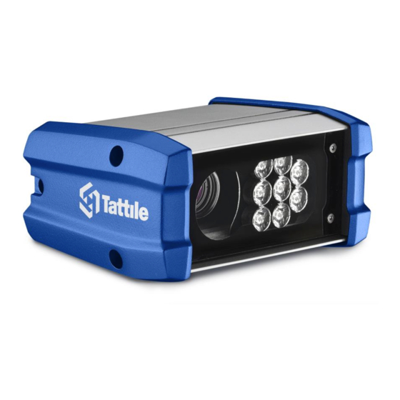
Page 4: General Description
Using External 24Vdc power supply Power supply voltage +24 -10% +24 +10% V (DC) Total power consumption Imaging and Illumination (Monochrome models F01750 - F01752) Image sensor Monochrome CMOS 2/3" Global Shutter Frame Rate 60 fps Image resolution 1920 x 1080 pixel Illuminator Infrared λ= 850 nm ±15nm... - Page 5 Number of LEDs 8 high power LEDs. Filter 375-660 nm Lenses C-mount (not included, must be ordered separately) Electronic characteristics Gigabit Ethernet 10/100/1000 Wi-Fi IEEE 802.11 b/g/n Single 2.4 GHz band RS485 insulated serial interface Wiegand communication port 2 digital optoisolated PNP input 2 Relay NO output 1 Strobe output Temperature and humidity sensor...
-
Page 6: Conformity - Compliance
/ Address 25030 Mairano (BS), Italy Dichiara sotto la propria responsabilità che i prodotti: / Declares under sole responsibility that the products: F01750, VEGA BASIC SHORT - MONO Modello, descrizione: / Model, description F01751, VEGA BASIC SHORT - COLOR F01752, VEGA BASIC LONG – MONO F01753, VEGA BASIC LONG - COLOR sono in conformità... - Page 7 Tattile herewith declares that this product is in compliance with the following US Federal Regulation: FCC 47 CFR Part 15 (Emission Class B) Contains FCC ID: QOQWF111 This device complies with Part 15 of the FCC Rules. Operation is subject to the following two conditions: (1) this device may not cause harmful interference, and (2) this device must accept any interference received, including interference that may cause undesired operation.
- Page 8 The hazard distance (HD) is the point furthest from the illuminator at which the Exempt Group exposure limit is exceeded. Illuminator risk group and hazard distance evaluation: F01750 IR illuminator lens 36° (wavelength 860nm, ±15nm spectral bandwidth @ 50% of max intensity) Hazard...
- Page 9 For illuminator exceeding Exempt Group limit camera shall be installed as detailed in the figure below, at distance L>HD, there is no risk to the public. Operator or maintenance staff working in front of the camera, facing the illuminator, at distance less than HD must use appropriate shielding or eye protection, as written in the labelling.
-
Page 10: Interfaces Characteristics
Interfaces characteristics Digital input Type Optoisolated PNP Channels Voltage 24 V DC Relay output Type Normally open Channels Max switching voltage 21 V AC / 30 V DC Max switching current 0.5 A Rev. D RMM_00042 2017-07-25... - Page 11 OUT1-COM V IN OUT1-NO Strobe output Type Optoisolated open collector Channels Max voltage 24 V DC +10% Min voltage 3.3 V DC -10% Max current 50 mA Rev. D RMM_00042 2017-07-25...
-
Page 12: Mechanical Dimensions
Mechanical dimensions Camera body Ref. Description Lens IR Illuminator Extruded body Cover Cable Glands Rev. D RMM_00042 2017-07-25... -
Page 13: Connections
Connections Connector Layout A - RJ45 Ethernet Socket B - Power Supply, Signal I/O Socket Power supply, Signal and I/O Connector Signal name Description OUT0-NO Relay Output 0, NO contact OUT0-COM Relay Output 0, COM contact OUT1-NO Relay Output 1, NO contact OUT1-COM Relay Output 1, COM contact STRB_OUT... -
Page 14: Gigabit Poe Ethernet Socket
Gigabit PoE Ethernet Socket RJ45 Gigabit connector 10/100 mode (10base- Gigabit mode (1000base-T) T/100base-TX) MX1+ MX1- MX2+ MX3+ MX4+ LED1 Link LED Link LED LED2 Activity LED Activity LED Mating connector RJ45 PLUG included Rev. D RMM_00042 2017-07-25... -
Page 15: Cabling The Device
Cabling the device 1) Remove the three M5 Allen-screws placed on the left side of the camera. 2) Remove the left cover being careful not to break the gasket. 3) Open the cable glands and insert the power/signals and Ethernet cables through them. 4) Make the connections following the pinouts indicated in the 5.1 &... - Page 16 To guarantee the best connection of the wires to the connector please use pin connectors. 5) Connect the cables to the device. Make sure you place and correctly bend the cable inside the compartment to prevent it from being damaged when closing the left cover. 6) Appropriately tighten the cable glands.
-
Page 17: Accessories
Accessories Pole-Mounting Adaptor Drawing Ordering Code Note Pole-Mounting Adaptor for poles with diameter T19841 between 65mm and 110mm. Mating Parts Kit Ordering Code Note Mating parts kit (included in the package) T19687 Power Supplier Ordering Code Note Power Supplier 24 V DC, 5 A F01836 Rev. -
Page 18: Product Label
Product label Ref. Description Tattile logo Product Part Number Product Name Product Serial Number Serial Number Barcode (code 128) Ethernet Mac Address Mac Address Barcode (code 128) Revision CE mark Rated Voltage and current, symbol for nature of supply Rev. D... -
Page 19: Instructions For A Correct Installation
Instructions for a correct installation To guarantee a good functioning of the device all the instructions contained in this manual must be respected. If the installation does not follow the instructions below, Tattile declines all responsibility for anomalous behaviours of the device: ... -
Page 20: Revisions
Revisions Rev. Date Description Prepared by Approved by Pre. A 2016-11-23 Preliminary Version P. Forti I. Paderno Updating of the Preliminary version, including Products Name, note about Pre. B 2017-02-24 P. Forti I. Paderno Power Supply PoE (page 4) added. New code of pole-mounting bracket Pre.
Need help?
Do you have a question about the F01750 and is the answer not in the manual?
Questions and answers