
Related Manuals for AccuMac AM8060


Summary of Contents for AccuMac AM8060
- Page 1 AM8060 Precision Thermometer User’s Guide Please download the latest version at www.accumac.com Rev. 202001V1...
-
Page 2: Table Of Contents
AM8060 Precision Thermometer User’s Guide Table of Contents Important Notice ---- Warning ..................2 Introduction ......................3 Main Application..................... 3 Main Features ....................3 Specifications ......................5 Specifications ....................5 Probe Types ....................5 User Interface ......................6 General Operations ....................7 Connecting the probes .................. -
Page 3: Important Notice
AM8060 Precision Thermometer User’s Guide Important Notice ---- Warning Check the position of the “Measurement/Calibration Switch” on the rear panel before turning on the device. Please refer to Figure 2. The switch must be at the measurement (left) position. Loss of calibration data will occur if the switch is at the calibration (CAL) position when the instrument is used in measurement application. -
Page 4: Introduction
AM8060 Precision Thermometer User’s Guide 1 Introduction The AM8060 precision thermometer is a dual-channel PRT readout. It can be used either as a temperature measurement device or a temperature reference standard. It is capable of working together with various types of platinum resistance thermometers (PRTs) and can measure temperatures from two probes simultaneously. - Page 5 AM8060 Precision Thermometer User’s Guide Wireless real time temperature data capturing with optional external wireless module (optional). Real time temperature data capturing and saving to flash drive. 4/41...
-
Page 6: Specifications
AM8060 Precision Thermometer User’s Guide 2 Specifications 2.1 Specifications Temperature range:-200 ºC ~ 850 ºC Resolution:0.001 ºC Accuracy: 25Ω SPRT/IPRT 100Ω SPRT/IPRT ±0.01 ºC @ -196 ºC ±0.010 ºC @ -200 ºC ±0.008 ºC @ 0 ºC ±0.008 ºC @ 0 ºC... -
Page 7: User Interface
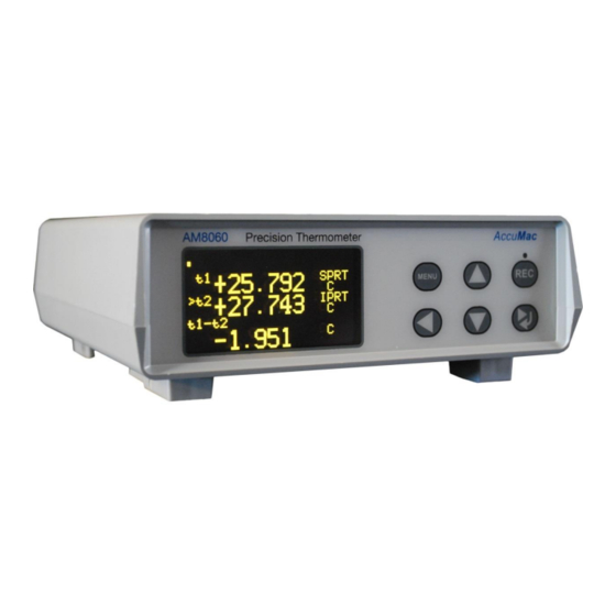
AM8060 Precision Thermometer User’s Guide 3 User Interface Front Panel : Display Main Menu U Drive recording Start/Stop button Left key Value Adj Right/Return Key Figure 1: Front Panel Rear Panel: U Drive Interface Probe 1(S1) terminals AC Power Inlet/Switch... -
Page 8: General Operations
4.1 Connecting the probes The AM8060 can work with one or two probes for temperature measurement. Figure 3 shows the rear panel of the AM8060. Probe 1 can be connected to terminals marked with S1, and Probe 2 to S2. - Page 9 Line 2, which is indicated with ‘t1’, shows the measured temperature of Probe 1 (S1). The“SPRT” at the end of the Line 2 tells the type of probe of Probe 1 (S1). The AM8060 supports two types of probes. “SPRT” indicates a 25Ω or 100 Ω standard platinum resistance thermometers.
-
Page 10: Selecting Units
Users can select to display ºC, ºF or Ω by scrolling touch keys up or down ( 4.5 Selecting Sensors/Probes and Adjusting Parameters 4.5.1 Probe Types AM8060 can work with different types of PRTs. Users can choose probe types and input the parameters of the probes. MENU The menu key... - Page 11 ITS-90 standard platinum resistance thermometer equations. If the probe is a standard platinum resistance thermometer, the probe will be displayed as “SPRT”. AM8060 calculates temperature according to ITS-90 standard platinum resistance thermometer equations. 4.5.2 Selecting Sensors/Probe and Parameters Input MENU 4.5.2.1...
- Page 12 AM8060 Precision Thermometer User’s Guide U-Drive Setting. Users can select this to change settings for saving data to an external drive. Wireless Setting. Users can select this to change the settings for wireless communication. Although only “Sensor 1 Setting” is illustrated below, the procedure of Sensor 1 and Sensor 2 adjustments are identical.
- Page 13 AM8060 Precision Thermometer User’s Guide 4.5.2.4 If the sensor type is SPRT, the adjustable parameters are Rtp, a, b, c, a4 and b4. The details of these parameter definitions can be found from the ITS-90. As an example, calibration agencies provide following parameters after SPRT is calibrated: Rtp: probe’s resistance at triple point of water.
- Page 14 AM8060 Precision Thermometer User’s Guide , , , MENU 4.5.2.5 keys can be used together to adjust these parameters. The parameters can also be saved into the instrument. The following is the procedure of adjusting and saving the parameters of Rtp and a4 for an SPRT type probe.
- Page 15 AM8060 Precision Thermometer User’s Guide cursor to “>SET a4”, and then press key to go into the a4 adjustment program, as seen below: [SENSOR 1 SPRT] --------------------------------------------- a4= - 4.129934e-05 SET a4=0 >ADJUST a4 MENU=Exit ENTER=Yes The second line (a4 = -4.129934e-05) displays the current a4 value, while the next two lines show the adjustment selections.
- Page 16 Other parameter adjustments are similar to the above Rtp and a4 adjustment. 4.5.2.12 After all of the desired adjustments are made, users can MENU go back to the main menu by pressing key multiple times until the AM8060 goes back to the main screen. 15/41...
-
Page 17: Instrument Calibration And Accuracy Adjustments
(S1) before calibrations. To calibrate AM8060 in the range from 10 Ω to 50 Ω, R0 (or Rtpw) needs to be set to 25 Ω. To calibrate AM8060 in the range from 50 Ω to 375 Ω, R0 (or Rtpw) needs to be set to 100 Ω. -
Page 18: 100 Ω Calibration
5.1.1 Turn off the power, put the measurement/calibration switch to the “CAL”side (right side). Please see Figure 3 for details. 5.1.2 After turning on the power,AM8060 shows the calibration main menu. It can be seen that there are two calibrations required: 100 Ohm CALIBRATION and 25 Ohm CALIBRATION. - Page 19 AM8060 Precision Thermometer User’s Guide 5.1.4 The instrument will show the phrase “Connect a 100 Ohm Standard Resistor and Press Enter” to indicate that a 100Ω standard resistor must be connected to sensor1 (S1) terminals as MENU Figure3. Users can exit the calibration by pressing key to go back to the main menu (*CALIBRATION MENU*).
-
Page 20: Ω Calibration
AM8060 Precision Thermometer User’s Guide 5.1.7 It is required to wait for 10 seconds for the data to be stable. Each second is shown with a blinking dot at the top left hand corner of the display. Once this is completed, the next step involves saving the calibrated data. - Page 21 AM8060 Precision Thermometer User’s Guide 5.2.3 Touch key to start the program of 25 Ohm CALIBRATION. The instrument will display the following message: * 25 Ohm CALIBRATION ------------------------------------------- Connect a 25 Ohm Standard Resistor and Press Enter Menu= Exit Enter = Yes 5.2.4 Follow the “Connect a 25 Ohm Standard Resistor and Press...
-
Page 22: Reset The Measurement/Calibration Switch After Calibration
AM8060 Precision Thermometer User’s Guide (underscore) to the desired, and using key to adjust the value. After the adjustment, the instrument will display: * 25 Ohm CALIBRATION 25R Rs = 24.9977 Rt =24.9977 Menu= Exit Enter = Yes 5.2.7 It is required to wait for 10 seconds to ensure the reading is stable. -
Page 23: Wireless Data Acquisition
6 Wireless Data Acquisition The AM8060 precision thermometer can transmit temperature data through a wireless transmission module. Free software for this feature is included with the AM8060. To transmit data wirelessly, users will need the followings: AM8060-W, precision thermometer with embedded wireless function. - Page 24 5) After the installation of the USB driver the user will need to install the free software on the CD included with the AM8060. Insert the CD into the computer’s CDROM drive and copy the file named CDrN_2xAir_Reader.exe to the computer.
- Page 25 Base RF OK” and “Wireless Remote OK” to confirm the wireless connection. The value after “ADDR” shows the wireless address of the AM8060. The value after “RSSI” is the wireless signal strength, which will not display until the user clicks on “Start”. The RSSI should be greater than - 99dBm.
- Page 26 AM8060 Precision Thermometer User’s Guide 9) The wireless data acquisition can be halted by clicking on “Stop”, or by clicking on “Exit” to quit the program. The default setting for a sampling period is 1 second. The data acquisition process can be restarted by clicking on “Start”.
- Page 27 AM8060 Precision Thermometer User’s Guide 11) The data saved in the file Air2x_data.txt will be in the following format: Time t1(C) t2(C) t1-t2(C) 16:23:19 -4.526 -84.456 79.930 16:23:20 -4.526 -84.456 79.930 16:23:21 -4.526 -84.456 79.930 end recording Time t1(C) t2(C) t1-t2(C) 10:48:45 -4.526...
- Page 28 AM8060 Precision Thermometer User’s Guide temperatures. The fourth column is the difference between Probe 1 and Probe 2. Each time “Stop” is pressed, the data saving will be halted, and the phrase “end recording” will be added to the file. To continue data saving, users can click on “REC”, and new data will be added to the last line of the...
-
Page 29: Using A Flash Drive ( U Disk ) For Data Acquisition
USB flash drive. There is a USB port on the rear panel of the AM8060 which can be used to store the measured temperature data to a flash drive. Any flash drive with size lower than 4 gigabytes can be connected to the “UDrive”... - Page 30 U2DATA.txt. 5) If users want to stop the data saving, just press key on the front panel. AM8060 will produce a short beep and the LED above key will be turned off to indicate the process has been halted.
- Page 31 1 and 65,535. The instructions for this are as follows: MENU A. When AM8060 is in a normal working state, press key and then hold key for 3 seconds. The AM8060 will display the...
- Page 32 N value. For example,the above picture shows the new N value as 9, which means the AM8060 will save data to the file every 9x1.21 seconds. To save this value, press and hold key and key.
- Page 33 AM8060 Precision Thermometer User’s Guide Note: The parameter adjustments should only be performed while the flash drive is not in the data saving process. 32/41...
-
Page 34: Using The Usb Interface For Data Acquisition
The following section describes the process of setting up a USB temperature data acquisition system: 1) Connect a USB cable to the USB (USB B type) port at the rear panel of the AM8060 digital thermometer to a computer. AM8060 Precision Thermometer Figure 5:AM8060 USB Temperature Data Acquisition System... - Page 35 AM8060 Precision Thermometer User’s Guide c. The measurement can be started by clicking on “Start”, stopped by clicking on “Stop”, or quit by clicking on “Exit”. The default sampling period is 1 second. The free software “CDRN_USBx2_Reader” also has a data saving function to save the captured temperature to a file, named “U_x2data.txt”.
- Page 36 AM8060 Precision Thermometer User’s Guide screen as the data is saved to the file, named “U_x2data.txt”. To stop the data saving, just click on “END” or “Stop”, and the temperature data saving will be stopped. The following figure shows that the data is saved to file with a sampling period of 3 seconds.
-
Page 37: Appendix: Installation Of Usb Driver
The installation of USB drivers are required the first time these instruments are connected to a computer. The USB drivers for the AM8060 precision thermometer and Wireless Transceiver are the same. The following steps describe the installation process: 1. - Page 38 AM8060 Precision Thermometer User’s Guide 3. Select “Install from a list or specific location (Advanced)” and then click “Next”. 4. Click “Browse” to select the CD drive containing the attached CD (in this example, the CDROM drive is E:), then click “Next”.
- Page 39 AM8060 Precision Thermometer User’s Guide 5. Select “Continue Anyway”. The computer will search for another file, called “FTD2XX.sys”. 6. Click “Browse” to find and select the file named “FTD2XX.sys”,and then click “OK”. After the installation, the computer will display the following screen:...
- Page 40 AM8060 Precision Thermometer User’s Guide 7. Click “Finish” to end the installation. 8. The computer will display a message saying, “Your new hardware is ready to use” to indicate the USB drivers are correctly installed. 39/41...
- Page 41 Each product from AccuMac Technology is warranted to be free from defects in material and workmanship under normal use and service. The warranty period is 1 year for Precision Thermometers. The warranty period begins on the date of the shipment.
Need help?
Do you have a question about the AM8060 and is the answer not in the manual?
Questions and answers