Advertisement
Quick Links
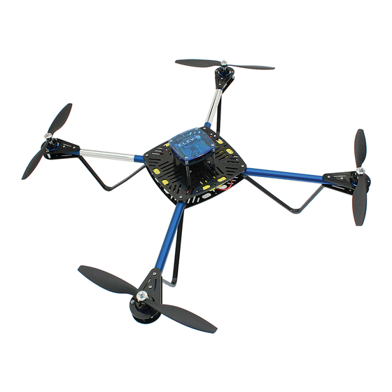
ELEV-8 V2 Quadcopter Assembly
Guide
Congratulations and thank you for purchasing a Parallax ELEV-8 Quadcopter, designed and
manufactured in California, USA. We at Parallax pride ourselves on producing high-quality
products with industry-leading documentation and support. These instructions are for
assembling the Parallax ELEV-8 Quadcopter Version 2 (#80200 or #80202) in its most standard
configuration.
If you have an ELEV-8 Quadcopter you must register it with the
Administration's UAS Registry
Do not use any assembly instructions or guides other than those provided by Parallax Inc. for
your exact part number. Doing so may result in hardware failure and/or personal injury. Also
note that there are small but extremely important differences between Version 1 (#80000) and
Version 2 (#80200/#80202) of the ELEV-8; do not use this web guide for assembling Version 1.
This assembly guide assumes your ELEV-8 V2 kit contains a flight controller (#80200). If you
bought the ELEV-8 V2 No Flight Controller kit (#80202), sections regarding the programming
and installation of the HoverFly Open will not apply to you. Watch for special announcements
on these pages as you progress through assembly.
This guide consists of thirty-nine discrete assembly steps, organized into nine sections. The
introduction page of each section will explain what will be done in the steps within and why, and
list all of the tools and parts you will need for that particular section. If you prefer to work from a
printed version of these instructions, p lease be advised - this PDF assembly guide is
extremely long and will take a large amount of paper when printed.
Copyright © Parallax Inc.
Web Site:
w ww.parallax.com
Learn:
l earn.parallax.com
Forums:
f orums.parallax.com
Sales:
s ales@parallax.com
Technical:
s upport@parallax.com
before flying outdoors.
ELEV-8 V2 Assembly Guide
Office: (916) 624-8333
Fax: (916) 624-8003
Sales: (888) 512-1024
Tech Support: (888) 997-8267
EDU Hotline: (916) 625-6801
F ederal Aviation
07/26/2018
Advertisement

Related Manuals for Parallax ELEV-8 V2


Summary of Contents for Parallax ELEV-8 V2
- Page 1 Administration's UAS Registry before flying outdoors. Do not use any assembly instructions or guides other than those provided by Parallax Inc. for your exact part number. Doing so may result in hardware failure and/or personal injury. Also note that there are small but extremely important differences between Version 1 (#80000) and Version 2 (#80200/#80202) of the ELEV-8;...
- Page 2 (Note: Because this product is discontinued, some parts may no longer be available. Parallax is not responsible for replacing parts from kits purchased from a source other than our webstore or through our sales team, or if the kit is no longer within the warranty period.
-
Page 3: Additional Items Required
● Ruler or Measuring Tape ● Soldering Iron (We recommend the Parallax Basic Soldering Kit, #700-10011) ● Rosin-Core Solder, see note in Section 1 (Also in the Parallax Basic Soldering Kit) ● Work-Holding Vise (Also in the Parallax Basic Soldering Kit) ●... - Page 4 Horizon Hobby, Inc. and Bachmann Industries, Inc. Hoverfly is a registered trademark of Hoverfly Technologies, Inc. Futaba is a registered trademark of Futaba Denshi Kogyo Kabushiki Kaisha Corporation of Japan. Hitec is a trademark or registered trademark of Hitec RCD USA, Inc. Copyright © Parallax Inc. ELEV-8 V2 Assembly Guide 07/26/2018...
- Page 5 Section 1: Soldering the Connections All steps in Section 1 will focus on the ELEV-8 V2 electrical connections. All of the high-current connections between components will be made using gold-plated bullet connectors (“male” and “female” on the left and right of the below image, respectively), which must be soldered onto the wires and covered with heat-shrink tubing.
- Page 6 ● 24 – 3.5 mm “Female” Bullet Connector (#450-00050) ● 4 – 30A Electronic Speed Controller (ESC) (#750-90009) ● 1 – EC3 "Male/Female" Connector Pair (#452-00088) ● 1 – LiPo Battery (Not Included) Copyright © Parallax Inc. ELEV-8 V2 Assembly Guide 07/26/2018...
- Page 7 1. Using the ruler or measuring tape and wire cutter, measure and cut 12 lengths of wire, each 12 inches (30.5 cm) long. 2. Using the wire strippers, remove 1/8” (3 mm) of insulation from b oth e nds to expose the metal wire. Copyright © Parallax Inc. ELEV-8 V2 Assembly Guide 07/26/2018...
- Page 8 At the end of this step, you should have some extra wire. You may want to cut a few short pieces from it and strip the ends. You can use it to practice soldering in the next step. Copyright © Parallax Inc. ELEV-8 V2 Assembly Guide 07/26/2018...
- Page 9 (you have extra of both). 1. Take the wire at the tip of each motor lead and twist it using your fingers to bring all of the individual wires together. Copyright © Parallax Inc. ELEV-8 V2 Assembly Guide 07/26/2018...
- Page 10 It may take some time (up to 15 seconds), but it should be clear when the solder suddenly starts to "flow" around the tip of the wire. If you have difficulties tinning Copyright © Parallax Inc. ELEV-8 V2 Assembly Guide 07/26/2018...
- Page 11 6. Hold the soldering iron to the small hole on the side of the “cup” of the bullet connector, and apply solder slowly into the “cup” until it is half full. Put the solder down. Copyright © Parallax Inc. ELEV-8 V2 Assembly Guide 07/26/2018...
- Page 12 “cup” and continue to hold the soldering iron to the hole for approximately 15 seconds. This will help to prevent a "cold" solder joint (poor quality, where the solder has not properly fused to both surfaces). Copyright © Parallax Inc. ELEV-8 V2 Assembly Guide 07/26/2018...
- Page 13 9. Repeat this process to solder a "male" bullet connector to each of the three leads on each Motor, for a total of twelve connections. Copyright © Parallax Inc. ELEV-8 V2 Assembly Guide 07/26/2018...
- Page 14 Copyright © Parallax Inc. ELEV-8 V2 Assembly Guide 07/26/2018...
- Page 15 Place a bullet connector into the vise, with the shallow “cup” end facing up. If you are using the block, clamp it into the vise and seat the bullet connector into the hole. Copyright © Parallax Inc. ELEV-8 V2 Assembly Guide 07/26/2018...
- Page 16 Remove the soldering iron, but hold the motor lead until the solder has cooled and set, approximately 10 seconds. 3. Solder a "female" bullet connector to the other end of each of the twelve extension wires, using the same procedure. Copyright © Parallax Inc. ELEV-8 V2 Assembly Guide 07/26/2018...
- Page 17 P lace a bullet connector into the vise, with the shallow “cup” end facing up. If you are using the block, clamp it into the vise and seat the bullet connector into the hole. Copyright © Parallax Inc. ELEV-8 V2 Assembly Guide 07/26/2018...
- Page 18 Remove the soldering iron, but hold the motor lead until the solder has cooled and set, approximately 10 seconds. 3. Solder "female" bullet connectors to the to the blue output leads on each ESC, using the same procedure. Copyright © Parallax Inc. ELEV-8 V2 Assembly Guide 07/26/2018...
- Page 19 Copyright © Parallax Inc. ELEV-8 V2 Assembly Guide 07/26/2018...
- Page 20 ● Small Flat-Head Screwdriver ● Flat-Nose Pliers Parts Needed ● 1 - Power Breakout Cable (#800-00006) ● 1 – "Male"/"Female" EC3 pair w/cover and bullet connectors (not interchangeable with other bullet connectors) (#452-00088) Copyright © Parallax Inc. ELEV-8 V2 Assembly Guide 07/26/2018...
- Page 21 1. Carefully cut the HXT connector off of the Power Breakout Cable just behind the connector. 2. Using the wire strippers, remove 1/8” (3 mm) of insulation from the end of the each lead. Copyright © Parallax Inc. ELEV-8 V2 Assembly Guide 07/26/2018...
- Page 22 (optional, not included) first might make the process easier. Repeat this "tinning" process with the other lead of the Power Breakout Cable. Copyright © Parallax Inc. ELEV-8 V2 Assembly Guide 07/26/2018...
- Page 23 “cup” until it is 1/3 full. Put the solder down. (try not to use too much solder in order to prevent excess solder from flowing to the outside of the bullet connector in the next instruction) Copyright © Parallax Inc. ELEV-8 V2 Assembly Guide 07/26/2018...
- Page 24 Use a sharp hobby knife (and extreme care) or a rotary tool with a grinding stone or cutting wheel to remove any excess solder from the outside of the bullet connector. Copyright © Parallax Inc. ELEV-8 V2 Assembly Guide 07/26/2018...
- Page 25 The red (positive) lead goes into the back of "D" shaped hole in the larger ("female") of the two housings (there are +/- markings on the housings as well). Copyright © Parallax Inc. ELEV-8 V2 Assembly Guide 07/26/2018...
- Page 26 “pop” when the bullet connector is properly locked into the plastic housing, and should appear as shown below. 14. Repeat steps 8 through 13 to solder another "male" bullet connector onto the other lead of your Power Breakout cable. Copyright © Parallax Inc. ELEV-8 V2 Assembly Guide 07/26/2018...
- Page 27 EC3 connector before getting started. You can skip this step if your battery came pre-installed with an EC3 connector. Even though the Parallax LiPo batteries (#752-00010) come with bullet connectors, they do not quite fit into the EC3 connector housings, so they have to be replaced.
- Page 28 3. Take the metal wire you just exposed and twist it using your fingers to bring all of the individual wire strands together. Copyright © Parallax Inc. ELEV-8 V2 Assembly Guide 07/26/2018...
- Page 29 (optional, not included) first might make the process easier. Repeat this "tinning" process with the other lead of the Power Breakout Cable. Copyright © Parallax Inc. ELEV-8 V2 Assembly Guide 07/26/2018...
- Page 30 9. Continuing to hold the soldering iron in place, bring the battery lead to connector and slowly insert into the cup. Copyright © Parallax Inc. ELEV-8 V2 Assembly Guide 07/26/2018...
- Page 31 11. Remove the soldering iron and continue to hold the wire until the solder hardens. Copyright © Parallax Inc. ELEV-8 V2 Assembly Guide 07/26/2018...
- Page 32 14. Repeat steps 1 through 13, this time to solder another "female" bullet connector onto the other lead of your battery. Copyright © Parallax Inc. ELEV-8 V2 Assembly Guide 07/26/2018...
- Page 33 ● 18” – Heat-shrink Tubing, 3/16" (#800-00023) Instructions 1. Using the ruler or measuring tape and scissors, measure and cut 32 lengths of heat-shrink tubing, each 1/2 inches (13 mm) long. Copyright © Parallax Inc. ELEV-8 V2 Assembly Guide 07/26/2018...
- Page 34 1. For the “female” bullet connectors on the ESCs and extension wires: slide a piece of 3/4" heat-shrink tubing (HST) onto the connector until it is flush with the end of the connector. Copyright © Parallax Inc. ELEV-8 V2 Assembly Guide 07/26/2018...
- Page 35 3. To shrink using a heat gun carefully apply heat to all sides of the connector until the HST stops shrinking, holding the tip of the heat gun about 1 -3 inches away, Copyright © Parallax Inc. ELEV-8 V2 Assembly Guide 07/26/2018...
- Page 36 6. Inspect all of the applied HST, they should appear as in the the first photo below with the check mark. All of the photos with X are examples of bad HST applications and should be re-done. Copyright © Parallax Inc. ELEV-8 V2 Assembly Guide 07/26/2018...
- Page 37 Results at end of this step: Copyright © Parallax Inc. ELEV-8 V2 Assembly Guide 07/26/2018...
- Page 38 ● 4 – Landing Gear (#721-80007), #11 in drawing below ● 16 – Machine Screw, M3-0.5 x 6mm (#710-00039), #12 in drawing below ● 8 – Locknut, #4-40 (#700-00024), #13 in drawing below Copyright © Parallax Inc. ELEV-8 V2 Assembly Guide 07/26/2018...
- Page 39 Copyright © Parallax Inc. ELEV-8 V2 Assembly Guide 07/26/2018...
- Page 40 ● 1 – Loctite® Threadlocker Blue 242® (#700-00106) Instructions 1. Using the hex key, carefully remove the motor set screw from each motor. The screws may be very tight; be careful not to break your hex key. Copyright © Parallax Inc. ELEV-8 V2 Assembly Guide 07/26/2018...
- Page 41 2. For each motor, apply a small amount of Loctite® to the set screw threads and carefully reinstall the screws. Seat each screw firmly but do not over-tighten. Allow the Loctite® to set for 10 minutes; it will fully cure in 24 hours. Copyright © Parallax Inc. ELEV-8 V2 Assembly Guide 07/26/2018...
- Page 42 Motor lead into the "female" bullet connector on an Extension wire, until fully seated. 2. Repeat this process to plug an Extension Wire into each lead of this motor, and then the three remaining motors. Copyright © Parallax Inc. ELEV-8 V2 Assembly Guide 07/26/2018...
- Page 43 2. One at a time, insert four screws into the innermost holes on the Motor Mount Bottom, making sure to line up with the threaded holes in the bottom of the Motor, and tighten with the screwdriver. Copyright © Parallax Inc. ELEV-8 V2 Assembly Guide 07/26/2018...
- Page 44 3. Repeat this process for the three remaining motors. Copyright © Parallax Inc. ELEV-8 V2 Assembly Guide 07/26/2018...
- Page 45 1. Slide a lock washer onto a screw, and then feed the screw through the hole on the side of a Top Motor Mount. 2. Apply a drop of Loctite® to the screw thread. Copyright © Parallax Inc. ELEV-8 V2 Assembly Guide 07/26/2018...
- Page 46 3. Screw on a standoff and tighten until snug using the pliers and screwdriver 4. Repeat this for the opposite side of the Top Motor Mount, and then for the three other Top Motor Mount. Copyright © Parallax Inc. ELEV-8 V2 Assembly Guide 07/26/2018...
- Page 47 Copyright © Parallax Inc. ELEV-8 V2 Assembly Guide 07/26/2018...
- Page 48 Bottom Motor Mount and line up with the holes on the sides. 2. Apply a drop of Loctite® to the top of the standoff through the hole in the Bottom Motor Mount. Copyright © Parallax Inc. ELEV-8 V2 Assembly Guide 07/26/2018...
- Page 49 3. Slide a lock washer onto a screw, feed the screw through the hole on the side of a Bottom Motor Mount, and screw into the standoff until snug. Copyright © Parallax Inc. ELEV-8 V2 Assembly Guide 07/26/2018...
- Page 50 4. Repeat this for the opposite side of the Motor Mount, and then for the three other Motor Mounts. Copyright © Parallax Inc. ELEV-8 V2 Assembly Guide 07/26/2018...
- Page 51 1. Use the pencil to make a small mark on the Booms 2 1/4” (5.7 cm) from the end of the Boom that has the holes closest together. 2. Cut the Chrome Sticker into two pieces, each measuring 5” (12.7 cm) by 2 1/4” (5.7 cm). Copyright © Parallax Inc. ELEV-8 V2 Assembly Guide 07/26/2018...
- Page 52 3. Peel the paper backing partially off, and line up with the pencil mark and the axis of the Boom, press lightly to adhere. 4. Slowly pull the backing off as you rotate the boom, pressing the sticker on as you go. 5. Repeat for the second Boom. Copyright © Parallax Inc. ELEV-8 V2 Assembly Guide 07/26/2018...
- Page 53 Boom end with the holes closest together. Note that the Extension Wires should come out of the end with the holes farther apart. 2. Repeat this for the other three Booms. Copyright © Parallax Inc. ELEV-8 V2 Assembly Guide 07/26/2018...
- Page 54 STOP. You are likely hitting the wires running through the Boom; “jiggle” things around or carefully twist the screw a couple of times until you can feed it all the way through with ease. Copyright © Parallax Inc. ELEV-8 V2 Assembly Guide 07/26/2018...
- Page 55 4. Take the short side of the Landing Gear and feed it over the other screw, followed by the other locknut. Tighten as described above. 5. Repeat Instructions 1-4 for the three remaining Booms. Copyright © Parallax Inc. ELEV-8 V2 Assembly Guide 07/26/2018...
- Page 56 ● 4 – Machine Screw, #4-40 x 1 1/4” (#710-00042) ● 4 – 30A Electronic Speed Controller (ESC), prepared in Step 7 ● 4 – Zip Tie, 4” Black (#700-00093) ● 1 – HXT to 3.5mm Power Breakout Cable (#800-00006) Copyright © Parallax Inc. ELEV-8 V2 Assembly Guide 07/26/2018...
- Page 57 Copyright © Parallax Inc. ELEV-8 V2 Assembly Guide 07/26/2018...
- Page 58 As a rule of thumb, tighten until you start to feel resistance, and then one more full turn. Copyright © Parallax Inc. ELEV-8 V2 Assembly Guide 07/26/2018...
- Page 59 2. Repeat this for the remaining three standoffs. Copyright © Parallax Inc. ELEV-8 V2 Assembly Guide 07/26/2018...
- Page 60 ● 8 – Saddle Washer, 3/4" (#712-00010)(#5 in the drawing below) ● 4 – Boom and Motor Assemblies, prepared in Step 15 (#6 in the drawing below) ● 8 – Aluminum Standoff, #4-40 x 1/8" (#700-00014)(#7 in the drawing below) Instructions Copyright © Parallax Inc. ELEV-8 V2 Assembly Guide 07/26/2018...
- Page 61 2. Feed one of each of the screws through their respective holes in the Top Frame Plate, so that the screw-heads are on the same side as the FC mount standoffs. 3. Slide a nylon spacer over each screw followed by a saddle washer. Copyright © Parallax Inc. ELEV-8 V2 Assembly Guide 07/26/2018...
- Page 62 Boom. 6. Repeat instructions 2 through 5 for the three remaining Booms, making sure that the two Booms with the Chrome Stickers are adjacent to one another Copyright © Parallax Inc. ELEV-8 V2 Assembly Guide 07/26/2018...
- Page 63 ● 4 – Zip Tie, 4” (#700-00093) Instructions 1. Using the image below as a guide for orientation, place one of the ESCs into one of the spaces on the Chassis plate between the Booms. Copyright © Parallax Inc. ELEV-8 V2 Assembly Guide 07/26/2018...
- Page 64 2. Thread a zip tie through the Chassis and around the ESC. Thread the tail of the zip tie into the fastener and pull until tight (you may use flat-nose pliers to tighten, if necessary). 3. Cut off the tail of the zip tie. Copyright © Parallax Inc. ELEV-8 V2 Assembly Guide 07/26/2018...
- Page 65 4. Repeat steps 1-3 to mount the three remaining ESCs. Copyright © Parallax Inc. ELEV-8 V2 Assembly Guide 07/26/2018...
- Page 66 ESC’s output leads. 3. Arrange the wires so that they appear exactly as in the figure below; this will make the rest of the wiring easier. Copyright © Parallax Inc. ELEV-8 V2 Assembly Guide 07/26/2018...
- Page 67 Copyright © Parallax Inc. ELEV-8 V2 Assembly Guide 07/26/2018...
- Page 68 (and forward direction) of the ELEV-8 is defined by the side of the Chassis between the two Chrome Booms, as shown in the image above (note that the quad is upside down in the image) Copyright © Parallax Inc. ELEV-8 V2 Assembly Guide 07/26/2018...
- Page 69 2. Using the above graphic for reference ( N ote the ELEV-8 is viewed from the TOP in the above labeled graphic ) , number the top and bottom of the corresponding ESCs and the signal cable connectors for the ESCs, as shown in the images below. Copyright © Parallax Inc. ELEV-8 V2 Assembly Guide 07/26/2018...
- Page 70 3. Now label the top of each Motor Mount with their number and an arrow indicating the direction of rotation, as shown in the image below. Copyright © Parallax Inc. ELEV-8 V2 Assembly Guide 07/26/2018...
- Page 71 Harness wires and all of the black ESC inputs are connected black Power Harness wires. No need to secure the Power Harness just yet; you will do that just before you attach the Bottom Chassis Plate. Copyright © Parallax Inc. ELEV-8 V2 Assembly Guide 07/26/2018...
-
Page 72: Flight Controller
The Flight Controller must also be set up before it can control the ELEV-8. Note: If you are working with a ELEV-8 V2 No Flight Controller kit (#80202), you will skip Step 24. It is for configuring the HoverflyOPEN flight controller O NLY . - Page 73 T-SIX transmitter in the following instructions. To get started, choose the your transmitter type from the list below. Once you have finished configuring your transmitter, scroll down the page to find the receiver binding instructions. ● Spektrum DX6i ● Spektrum DX7 Copyright © Parallax Inc. ELEV-8 V2 Assembly Guide 07/26/2018...
- Page 74 Mode” switch to 1, click once, scroll until the screen reads “25%,” click again to save. Y ou will need to keep this switch in the “1” position for normal flight operation. Copyright © Parallax Inc. ELEV-8 V2 Assembly Guide 07/26/2018...
- Page 75 5. Scroll to “Model Name” and click once. Use the roller to name your model (we suggest “ELEV-8 V2”); scroll until the cursor is under the character you wish to edit, then click once; scroll until the character you want appears, then click again to save. Scroll to move the cursor to the next character and repeat.
- Page 76 4. Scroll to “Model Name” and click once. Use the roller to name your model (we suggest “ELEV-8 V2”); scroll until the cursor is under the character you wish to edit, the click once; scroll until the character you want appears, then click again to save. Scroll to move the cursor to the next character and repeat.
- Page 77 LED on the receiver stops flashing. (You may need to be at least 6 feet (2m) away from the receiver). 6. Unplug the battery, r emove the bind plug , and turn off your transmitter. Copyright © Parallax Inc. ELEV-8 V2 Assembly Guide 07/26/2018...
- Page 78 5. Once the status LED stops flashing, binding is complete. 6. Unplug your battery, remove the ESC, and binding plug. Copyright © Parallax Inc. ELEV-8 V2 Assembly Guide 07/26/2018...
- Page 79 5. Compare the direction of rotation you noted with what is shown in the diagram below. If the Motor spun in the correct direction (as indicated by the diagram), skip to Instruction Copyright © Parallax Inc. ELEV-8 V2 Assembly Guide 07/26/2018...
- Page 80 ESC corresponding to (matching the number of) the Motor in question. 7. Locate any two of the (three) blue Extension Wires running to the ESC and unplug them from the ESC. Copyright © Parallax Inc. ELEV-8 V2 Assembly Guide 07/26/2018...
- Page 81 8. S witch the Extension Wires for one another, and plug them back in. You have now reversed (corrected) the Motor’s spin direction. 9. Repeat Instructions 1-8 as necessary for the three remaining Motors/ESCs. Copyright © Parallax Inc. ELEV-8 V2 Assembly Guide 07/26/2018...
- Page 82 The Flight Controller (FC), in this case the HoverflyOPEN, is the "brain" of the ELEV-8. The Parallax Propeller 1 microcontroller mounted on it receives signals from the radio receiver that it processes, in conjunction with data from the onboard three-axis gyroscope, to keep the ELEV-8 in stable flight.
- Page 83 14. Once the flash has finished and the "Flash Log" reads "Success", you may disconnect your board from your computer and exit the Hoverfly Update Client. 15. Return the HoverflyOPEN to its ESD-safe bag. Copyright © Parallax Inc. ELEV-8 V2 Assembly Guide 07/26/2018...
- Page 84 ● ELEV-8 assembly, prepared in Step 21 ● 4 – Zip Tie, 4” (#700-00093) ● 1 – Bottom Chassis Plate (#721-80003) ● 8 – Saddle Washer, 3/4” (#712-00010) ● 8 – Locknut, #4-40 (#700-00024) Copyright © Parallax Inc. ELEV-8 V2 Assembly Guide 07/26/2018...
- Page 85 2. Feed the signal cable from the #3 ESC underneath the Wire Harness and the blue wires, towards the center of the Chassis. 3. Now feed the cable towards the #2 ESC, keeping it under the wire harness and all the blue wires, as shown below. Copyright © Parallax Inc. ELEV-8 V2 Assembly Guide 07/26/2018...
- Page 86 4. Repeat Instructions 2 and 3 with ESCs #1 and #4; feeding the signal cable to the center and then towards ESC #2. 5. One by one, push the wires through one of the slots in the Top Chassis Plate just to the right of the ESC #2. Copyright © Parallax Inc. ELEV-8 V2 Assembly Guide 07/26/2018...
- Page 87 Copyright © Parallax Inc. ELEV-8 V2 Assembly Guide 07/26/2018...
- Page 88 1. Orient the ELEV-8 so that it is upside-down and facing away from you. Situate the Wire Harness so that it matches the image below. Be sure that only the blue ESC output wires run over the Booms. Copyright © Parallax Inc. ELEV-8 V2 Assembly Guide 07/26/2018...
- Page 89 2. Use a zip tie to secure the Extension Wires running into Boom #4 to the input wires for ESC #1. 3. Use another zip tie to secure the Extension Wires running into Boom #1 to the input wires for ESC #2. Copyright © Parallax Inc. ELEV-8 V2 Assembly Guide 07/26/2018...
- Page 90 4. Use another zip tie to secure the Extension Wires running into Boom #2 to the input wires for ESC #3. 5. Use another zip tie to secure the Extension Wires running into Boom #1 to the input wires for ESC #4 and the Wire Harness. Copyright © Parallax Inc. ELEV-8 V2 Assembly Guide 07/26/2018...
- Page 91 Copyright © Parallax Inc. ELEV-8 V2 Assembly Guide 07/26/2018...
- Page 92 ● 4 – ELEV-8 assembly, prepared in Step 26 (#4 in drawing below) Instructions 1. Orient the ELEV-8 so that it is upside-down and facing away from you. 2. Place a saddle washer over each of the screws running through the Booms. Copyright © Parallax Inc. ELEV-8 V2 Assembly Guide 07/26/2018...
- Page 93 4. Thread locknuts onto the four center screws (no need to tighten yet). 5. Place the Landing Gear over the outer screws. 6. Thread locknuts onto the four outer screws. Copyright © Parallax Inc. ELEV-8 V2 Assembly Guide 07/26/2018...
- Page 94 7. Use the wrench to tighten all 8 screws. You will need to use the screwdriver to keep the screw-heads (on Top Chassis Plate) from spinning. Copyright © Parallax Inc. ELEV-8 V2 Assembly Guide 07/26/2018...
- Page 95 . Use caution if attempting to adapt some or all of these directions for any other control board. Parallax accepts no liability for the use of these directions with components not sold or provided by Parallax for your specific kit.
- Page 96 Copyright © Parallax Inc. ELEV-8 V2 Assembly Guide 07/26/2018...
- Page 97 . Use caution if attempting to adapt some or all of these directions for any other control board. Parallax accepts no liability for the use of these directions with components not sold or provided by Parallax for your specific kit.
- Page 98 Copyright © Parallax Inc. ELEV-8 V2 Assembly Guide 07/26/2018...
- Page 99 . Use caution if attempting to adapt some or all of these directions for any other control board. Parallax accepts no liability for the use of these directions with components not sold or provided by Parallax for your specific kit.
- Page 100 Instructions 1. Place the HoverflyOPEN over the Mount Plate and line up the screw holes. Copyright © Parallax Inc. ELEV-8 V2 Assembly Guide 07/26/2018...
- Page 101 2. Slide a washer over a screw, and insert through one of the four holes on the HoverflyOPEN and Mount Plate. 3. Thread on a locknut and tighten just until there is no longer a gap. Do not over tighten such that the grommet begins to compress. Copyright © Parallax Inc. ELEV-8 V2 Assembly Guide 07/26/2018...
- Page 102 4. Repeat instructions 2 and 3 for the remaining holes. Copyright © Parallax Inc. ELEV-8 V2 Assembly Guide 07/26/2018...
- Page 103 . Use caution if attempting to adapt some or all of these directions for any other control board. Parallax accepts no liability for the use of these directions with components not sold or provided by Parallax for your specific kit.
- Page 104 1. Orient the ELEV-8 so that it is upright and facing away from you (the Booms with Chrome Stickers are farthest from you). 2. Slide the four screws through the FC Top Plate, then slide on the four spacers. Copyright © Parallax Inc. ELEV-8 V2 Assembly Guide 07/26/2018...
- Page 105 ELEV-8 oriented as instructed above, the arrow on the FC must point away from you (towards the front of the ELEV-8). 5. Thread the screws into the standoffs with your screwdriver, just until snug. Do not overtighten. Copyright © Parallax Inc. ELEV-8 V2 Assembly Guide 07/26/2018...
- Page 106 Step 31: Connect ESC Signal Cables to Flight Controller Important! I f you have the ELEV-8 V2 No Flight Controller kit (#80202): the directions in Section 7 are specifically meant for installing and connecting the HoverFly OPEN control board only...
- Page 107 Copyright © Parallax Inc. ELEV-8 V2 Assembly Guide 07/26/2018...
- Page 108 . Use caution if attempting to adapt some or all of these directions for any other control board. Parallax accepts no liability for the use of these directions with components not sold or provided by Parallax for your specific kit.
- Page 109 This can be done by either shaving the two corners down with a sharp blade, or sanding them with sandpaper. The result should appear as shown in the third image below. Copyright © Parallax Inc. ELEV-8 V2 Assembly Guide 07/26/2018...
- Page 110 Flight Controller (below where "Reciever Port" is written on the top plate). 5. Using the image below as a reference, carefully plug the cables in, paying close attention to orientation and order. Copyright © Parallax Inc. ELEV-8 V2 Assembly Guide 07/26/2018...
- Page 111 . Use caution if attempting to adapt some or all of these directions for any other control board. Parallax accepts no liability for the use of these directions with components not sold or provided by Parallax for your specific kit.
- Page 112 3. Place the receiver in the zip tie and tighten. 4. Cut off the “tail” of the zip tie. Copyright © Parallax Inc. ELEV-8 V2 Assembly Guide 07/26/2018...
- Page 113 Instructions for Satellite Receiver If your Receiver came with a satellite module, you can mount it as shown below. Copyright © Parallax Inc. ELEV-8 V2 Assembly Guide 07/26/2018...
- Page 114 Copyright © Parallax Inc. ELEV-8 V2 Assembly Guide 07/26/2018...
-
Page 115: Section 8: Attaching The Battery
● 2 – Adhesive-Backed Foam Padding, approximately 1" (2.5 cm) wide, 2" (5 cm) long, and 3/8" (1cm) thick, ( o ptional , weather-stripping works great) ● 1 – LiPo Battery, prepared in Step 5 Copyright © Parallax Inc. ELEV-8 V2 Assembly Guide 07/26/2018... - Page 116 2. Remove the protective paper backing from one of the pieces of Foam Padding and attach to the Top Chassis Plate just behind the Flight Controller, as shown in the figure below. 3. Turn the ELEV-8 around so that it is now facing you. Copyright © Parallax Inc. ELEV-8 V2 Assembly Guide 07/26/2018...
- Page 117 4. Remove the protective paper backing from the other piece of Foam Padding and attach to the Top Chassis Plate just in front of the Flight Controller, as shown in the figure below. Copyright © Parallax Inc. ELEV-8 V2 Assembly Guide 07/26/2018...
- Page 118 Plate shown in the image below, and all the way through the Chassis. 3. Insert the strap back into a slot six spaces away from the current one, and feed it up through the Chassis. Copyright © Parallax Inc. ELEV-8 V2 Assembly Guide 07/26/2018...
- Page 119 4. Turn the ELEV-8 so that it is upright and facing away from you. 5. Use the same procedure to install a second strap on the side of the Flight Controller now facing you. Copyright © Parallax Inc. ELEV-8 V2 Assembly Guide 07/26/2018...
- Page 120 2. Slide the battery under the Flight Controller mount, so that the battery leads face the back of the ELEV-8. 3. Take one end of the strap in each hand and pull firmly apart and slightly up to tighten, and then push down to secure. Copyright © Parallax Inc. ELEV-8 V2 Assembly Guide 07/26/2018...
- Page 121 4. Repeat instructions 2-3 for the remaining battery strap. Copyright © Parallax Inc. ELEV-8 V2 Assembly Guide 07/26/2018...
- Page 122 ● 4 - Propeller Spacer Ring, included with each propeller (#5 in assembly drawing below) ● 4 – Propeller Adapters, included with each motor (#6 in assembly drawing below) ● ELEV-8 Assembly, prepared in Step 36 (#7 in assembly drawing below) Copyright © Parallax Inc. ELEV-8 V2 Assembly Guide 07/26/2018...
- Page 123 Copyright © Parallax Inc. ELEV-8 V2 Assembly Guide 07/26/2018...
- Page 124 ○ For Spektrum DX6i and ORX T-SIX transmitters, hold the scroll wheel down while powering on the system to access the “Setup List”, then scroll down to “Range Check” and click again. Copyright © Parallax Inc. ELEV-8 V2 Assembly Guide 07/26/2018...
- Page 125 If you do not have full control, do not fly the model! Some component of your system is malfunctioning and you should begin troubleshooting. Copyright © Parallax Inc. ELEV-8 V2 Assembly Guide 07/26/2018...
- Page 126 1. Remove the nut and washer from the top of each Propeller adapter and set aside for use in the next step. 2. Place a Propeller adapter over the top of a Motor, and align the screw holes with the motor. Copyright © Parallax Inc. ELEV-8 V2 Assembly Guide 07/26/2018...
- Page 127 3. Use the supplied screws to secure the Propeller adapter to the motor with the screwdriver. Tighten each screw until you begin to feel resistance, and then turn 1/8 of a turn more. 4. Repeat for the remaining three motors. Copyright © Parallax Inc. ELEV-8 V2 Assembly Guide 07/26/2018...
- Page 128 ● 4 - Propeller Spacer Ring, included with each propeller (#5 in assembly drawing below) Instructions 1. Remove the spacer rings from the Propeller bags and place the one indicated in the figure below over each Propeller adapter shaft. Copyright © Parallax Inc. ELEV-8 V2 Assembly Guide 07/26/2018...
- Page 129 Propeller, and the resistance increases; then tighten another 1/4 turn. 3. Using the same procedure, attach a 1045C Propeller to Motor #3. Attach a 1045CR Propeller to Motors #2 and #4. Copyright © Parallax Inc. ELEV-8 V2 Assembly Guide 07/26/2018...
- Page 130 Copyright © Parallax Inc. ELEV-8 V2 Assembly Guide 07/26/2018...
Need help?
Do you have a question about the ELEV-8 V2 and is the answer not in the manual?
Questions and answers