Table of Contents
Advertisement
Advertisement
Table of Contents

Related Manuals for CommScope PowerShift V1

Summary of Contents for CommScope PowerShift V1
- Page 1 User Manual ® PowerShift Document #7761739 Version B...
- Page 2 1. General DISCLAIMER: This document has been developed by CommScope, and is intended for the use of its customers and customer support personnel. The information in this document is subject to change without notice. While every effort has been made to eliminate errors, CommScope disclaims liability for any difficulties arising from the interpretation of the information contained herein.
-
Page 3: Table Of Contents
1. General TABLE OF CONTENTS 1. GENERAL ABOUT COMMSCOPE ® 2. POWERSHIFT TECHNICAL SUPPORT 3. REFERENCES 4. INTRODUCTION 4.1. PURPOSE 4.2. BENEFITS 4.3. SYSTEM COMPONENTS 4.4. GRAPHICAL USER INTERFACE (GUI) 5. SYSTEM OPERATION 5.1. GENERAL OPERATING DESCRIPTION 5.2. LED STATUS INDICATORS 5.3. - Page 4 1. General Page 4 PowerShift User Manual Version B...
-
Page 5: General
1. General 1. General About CommScope CommScope is the foremost supplier of one-stop, end-to-end radio frequency (RF) solutions. Part of the CommScope portfolio are complete solutions for wireless infrastructure from top-of-the-tower base station antennas to cable systems and cabinets, RF site solutions, signal distribution, and network optimization. For patents related to this, and other CommScope products, see www.cs-pat.com. -
Page 6: Introduction
• Future proof: Increase in radio power requirements may not require larger or additional power cables to be installed. • More Information: Visit the PowerShift product web page and video overview: http://www.commscope.com/solutions/power-solutions/ https://www.youtube.com/watch?v=FSJR6aNzHO4. 4.3. System Components The PowerShift System consists of the following components:... -
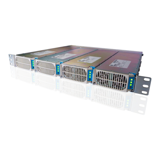
Page 7: Figure 4-1 Powershift Base Unit
4. Introduction Component Name Part Number Base Unit Shelf PS-1-R Base Unit Power Module PS-1-73 Capacitive Jumper DPJ-210CAP-3M PowerShift Base Unit Figure 4-1 PowerShift Base Unit Base Unit Features • The Base Unit is typically collocated with the existing DC power plant (e.g., installed in or near the DC power plant cabinet) •... -
Page 8: Graphical User Interface (Gui)
4.4. Graphical User Interface (GUI) The PowerShift V1 GUI is an executable file that is run on a Windows PC and connects to the PowerShift shelf via a custom RS485 interface cable. Contact customer technical support to obtain the software file and the document PowerShift Graphical User Interface Manual for additional details. -
Page 9: System Operation
5. System Operation 5. System Operation 5.1. General Operating Description The diagram below provides a basic operating description of an installed PowerShift system. Note that each Base Unit module has three circuits, and each circuit has its own input and output terminals; the three circuits operate independently from one another. -
Page 10: Led Status Indicators
5. System Operation c. When input power is applied to a circuit, the module executes a startup calibration mode only for that circuit (the other two circuits are not impacted); it calculates the round-trip resistance between the module output and the capacitive jumper at the far end of the cable d. -
Page 11: Form C Alarm Dry Contacts
5. System Operation Figure 5-2 LED Status Indicators b. LEDs 1, 2 and 3 provides the individual status of each of the three power circuits in the module c. LED X represents the status of the overall module d. Intermittent or latent failures will be indicated by the LED X indicator, even if the individual circuit LEDs are functioning correctly e. -
Page 12: Dip Switch And Data Interface
5. System Operation 5.4. DIP Switch and Data Interface As shown below, each base unit has a DIP switch and RJ45 interface ports. Figure 5-4 DIP Switch and Data Interface Ports DIP Switches a. The DIP switches are not for customer use, they should be left in the down position (factory default setting) RJ45 Data Ports a. -
Page 13: Operating Faults & Alarms
5. System Operation 5.5. Operating Faults & Alarms The following table lists the possible states for the LED status indicators, shows the corresponding state of the Form C alarm dry contacts, and provides troubleshooting comments for understanding resolving alarm conditions. Table 5-1 LED States and Alarm Contact Closures Circuit Module... - Page 14 5. System Operation Circuit Module Alarm Condition 1, 2 or 3 “X” LED Description (GUI & Relay) Green Solid Circuit is performing line resistance measurement Blink Green None Nominal condition (no alarm) – 30 second duration (<30 sec) Circuit is measuring the line resistance, it takes ~30 seconds to complete Occurs whenever circuit input power is applied or is cycled off/on Remote is not powered during this time -Or-...
- Page 15 5. System Operation Circuit Module Alarm Condition 1, 2 or 3 “X” LED Description (GUI & Relay) Solid Yellow Major Circuits are functioning, but a module-level fault has occurred. Green Solid The condition may not require immediate attention and can be corrected in the next available service window (e.g., the module can continue to run with the failure of one fan, until the module can be replaced).
- Page 16 5. System Operation Circuit Module Alarm Condition 1, 2 or 3 “X” LED Description (GUI & Relay) Possible cause – Module is over temperature - Module shuts down affected circuit(s) to protect itself from high temperature condition - Possible causes: Module fan intake is blocked, site shelter cooling system has failed, module fan has failed - If the problem resolves itself (shelter cooling is restored) and module drops below threshold, then output power is restored and LED status changes (see...
- Page 17 5. System Operation Circuit Module Alarm Condition 1, 2 or 3 “X” LED Description (GUI & Relay) - Module was previously shutdown to protect itself from high temperature condition, but the high temperature subsequently cleared - The circuit output power is re-enabled, but alarm is latched to provide site technician with clarity on which module and circuits were impacted - Possible causes: Module fan intake were temporarily blocked, site shelter cooling system was temporarily failed...
- Page 18 5. System Operation Circuit Module Alarm Condition 1, 2 or 3 “X” LED Description (GUI & Relay) Note: A red blink circuit LED can occur if the input power is cycled off and immediately back on, and there is no load (radio) connected to the circuit. In this case the capacitive jumper retains a small amount of voltage, and the module must allow it to discharge down before it can start the line resistance measurement.
-
Page 19: Installation Planning
6. Installation Planning 6. Installation Planning Following are general guidelines to plan the installation of the PowerShift system. For detailed, site-specific installation planning see the product web page referenced in Section 3. 6.1. Reference Schematic The following schematic provides a general reference for PowerShift installation planning. -
Page 20: Powershift Web Site
6. Installation Planning 6.2. PowerShift Web Site a. Check the CommScope website referenced in Section 3 to familiarize yourself with the different installation kits and options as part of your planning process 6.3. Perform A Site Walk a. Perform a site walk to evaluate and plan for the installation of the PowerShift system b. -
Page 21: Capacitive Jumper Installation Planning
6. Installation Planning • Allow additional space for at least 1” clearance in the front of the Base Unit (for fan air flow) • Evaluate whether straight, right-angle or 45-deg angle lugs are required in order for cables to clear any other rack hardware mounted directly below the Base Unit;... -
Page 22: Installation Guidelines
7. Installation Guidelines 7. Installation Guidelines IMPORTANT: For detailed installation procedures see the product web page referenced in Section 3. The following information provides general guidelines for on-site installation of the PowerShift system. 7.1. Test Tools In addition to the standard tools used for hardware installation, the following additional tools are useful for PowerShift installation testing. - Page 23 7. Installation Guidelines g. To troubleshoot any issues or when ready to connect the Remote, it will be necessary to power off the circuit. Note the following: NOTE: After powering off the circuit, wait about 2-3 minutes for the capacitive jumper to discharge before proceeding. The capacitor voltage will always be less than 60VDC safety limit (and thus there is no personal safety issue), but waiting a few minutes will minimize any negligible spark that may occur when the cable is reconnected to the RRU.
-
Page 24: Product Specifications
8. Product Specifications 8. Product Specifications For product specifications see the product web page referenced in Section 3. Page 24 PowerShift User Manual Version B...
Need help?
Do you have a question about the PowerShift V1 and is the answer not in the manual?
Questions and answers