Table of Contents
Advertisement
Quick Links
Advertisement
Table of Contents

Related Manuals for Formax Atlas C102

Summary of Contents for Formax Atlas C102
- Page 1 Atlas C102 Auto-Feed High-Speed Creaser OPERATOR MANUAL Second Edition 12/2019...
- Page 2 INDEX INTRODUCTION The Atlas C102 Creaser PAGE SAFETY Do’s & Don’ts THE ATLAS C102 CREASER Labeled Picture THE CONTROLS The switch panel Features on the switch panel QUICK START GUIDE SCREEN CALIBRATION OPERATING THE MACHINE Setting the machine Setting up a job Loading &...
-
Page 3: Specification
The Atlas C102 is a fully automatic suction feeding creasing system designed for use with both conventional litho and digital printers. The feed on the Atlas C102 can also be manually operated for use with heavy stock, very small or very large sheets, embossed or even irregular sheets. -
Page 4: Safety Do's & Don'ts
Safety Do’s & Don’ts Safety Do’s & Don’ts REGLES DE SECURITE : « A FAIRE » ET « A NE PAS FAIRE » Do - read this operator manual fully before operating the machine. Lire ce mode d'emploi avant d'utiliser la machine. Do - operate with the designated AC current only. -
Page 5: Warning Labels
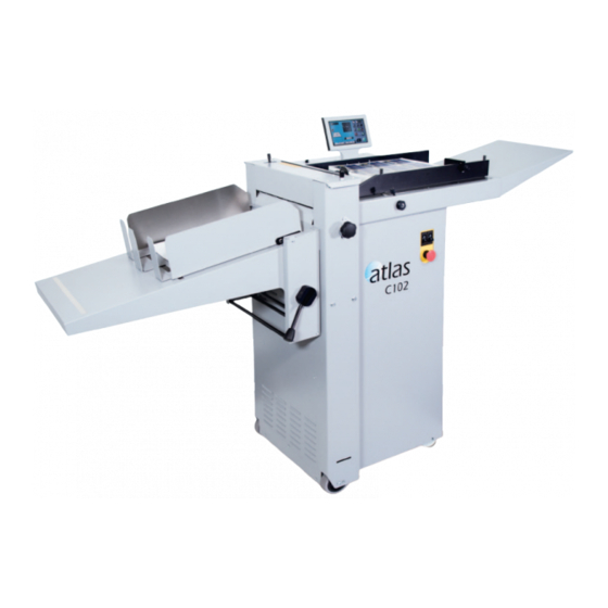
Warning Labels Do - be aware of any finger traps and rotating parts when operating the machine. Attention au risque de se coincer les doigts, et aux pièces en mouvement lors du fonctionnement de la machine. Do - read this operator manual fully before operating the machine. Lire ce mode d’emploi avant d’utiliser la machine. - Page 6 Atlas C102 DOCUMENT CREASING MACHINE Key to photograph below Roller tilt handle 6 Air separation knob Paper Gate Height Adj. Stacker Assy. 7 Adjustable side lay Exit Guard Suction slot knob 8 Back stop Switch Panel Touchscreen 9 Fixed side lay...
- Page 7 THE CONTROLS THE SWITCH PANEL The Switch Panel houses the Compressor switch, System switch, and an industry standard Emergency Stop switch which will stop all power going to the machine when activated. Compressor Switch System Switch Emergency Stop Switch Features on the Switch Panel System switch When activated the system switch will operate the motors in order to begin the creasing sequence.
- Page 8 Quick Start Guide Setting the machine to operate in automatic sheet feed mode Set the gap between the paper gate and the vacuum roller to approximately twice the thickness of the stock to be creased. Place the stock to be creased onto the loading table against the fixed side lay. Release the clamps on the adjustable side lay and slide up to the paper stack allowing a gap of approximately 0.5mm (1/64 inch) between the paper and the side lay.
- Page 9 Quick Start Guide The touch screen is laid out into 3 main areas as shown below: Status of Setting machine & page data entry area. Also used for quick links to setting pages. Tabs to enable switching between setting pages - choose either Paper Settings, Crease Setting, Store or Tools Settings Pages.
- Page 10 Quick Start Guide Crease settings Pages. To get to the crease setting page click the lower tab from the status area. If you have selected a predefined standard crease type from the paper settings page the crease positions will be set for you. These positions can be fine tuned by ±...
- Page 11 Quick Start Guide Creasing turned off - Greyed out areas are unselectable. Status area will show creasing is off with red icon SYSTEM Page 11...
- Page 12 Quick Start Guide Run Job Click to start machine with settings currently shown - you will receive a notification if system switch is not on. Press again to stop Job System Switch Not On Push System Switch down to start the machine. The machine running screen will appear.
- Page 13 Quick Start Guide Cover Crease Mode. 1. Select the Paper Settings Tab. 2. Enter the Paper Length and then select the Cover Crease button. Cover Crease button Paper Length 3. Select the Crease Settings Tab. Spine Offset Spine Width Hinge Distance Arrow Button 4.
- Page 14 Quick Start Guide Cross Perforating (Optional). 1. A cross perforating kit is available as an optional part, the blades available are: Full Width - Coarse Full Width - Fine 150mm - Coarse 150mm - Fine 100mm - Coarse 100mm - Fine 50mm - Coarse 50mm - Fine Refer to page 38 for fitting of the perforator blade set.
- Page 15 Quick Start Guide 6. Enter the Hinge Dimension. Hinge Dimension 7. Select the arrow button to highlight the Spine Offset and the Spine Width dimensions. 8. Run the sheets of paper through the machine to make the Spine creases. TO MAKE THE HINGE CREASES. 9.
-
Page 16: Status Screen
Quick Start Guide Status Screen Currently selected Vacuum Suck setting - for stream setting choose selection 2 Paper length - input from Touching in this area will take you the paper setting screen to the paper setting page Currently selected fold type - can be one of the following. - Page 17 Quick Start Guide The Status Screen will on occasions be replaced with an Input Calculator Screen as shown below. Pre - set Paper sizes for quick Pre - set Batch sizes for quick insertion – Standard sizes for insertion. country origin would be shown Paper size Batch size Crease position...
-
Page 18: Tools Screen
Quick Start Guide Tools Screen Machine Speed Adjustment:- Speed setting 3 will give the fastest throughput of stock through the machine. Use speed setting 1 or 2 for troublesome stocks. Click on Up Arrow to put Anvil into Top Dead Centre position Inch paper in direction (TDC) of arrow to clear jams... -
Page 19: Screen Calibration
Screen Calibration Touch Screen Calibration. Switch the mains power on and wait for the main screen to appear before commencing to check the horizontal and vertical position of the display. The position of the display within the surround is achieved by operating the button at the rear of the housing, press this a number of times to obtain the correct orientation required, move to the next button to move the position to centralize horizontal. -
Page 20: Operating The Machine
Operating The Machine Setting the Adjustable Side Lay Place the paper stack on to the loading table and slide up to the fixed side lay and paper gate. Release the clamps located at each end of the side lay and slide up towards the paper stack as demonstrated in Fig. - Page 21 Operating The Machine Setting the Machine Adjusting the Paper Gate Set the height of the Paper Gate to approximately two thicknesses of paper, by turning the disc j. An excessive gap is a most likely cause of double sheet feeding. This setting is only intended as a guide, for instance, sheets with an upward curl will require this setting to be increased.
- Page 22 Operating The Machine Setting the Roller Tilt Mechanism The roller tilt mechanism has been designed to compensate for when the creasing position on the sheet is not square. This could be due to an inaccuracy in the media or if the roller tilt mechanism has been incorrectly set.
- Page 23 Operating The Machine FIG. 3 Set Feed The length of suction on the sheet of paper being fed can be adjusted by setting the feed type as follows:- Select 1 for short suck, select 2 for continuous suck (stream feeding). Vacuum Suck Select 1 for short suck Select 2 for continuous suck...
- Page 24 Operating The Machine Setting up a job Switch the power ‘on’ by turning the Emergency stop button clockwise to release the safety latch. Setting the page length Set the page length of the paper as described on page 10. Setting the vacuum suck Set the vacuum suck as described on page 10.
- Page 25 Operating The Machine Loading & Saving Jobs Keyboard for entering job name. Delete all characters Delete last character to save click save icon job to store Save confirmation screen. To confirm saving of Job click here. Search for current jobs to load or modify. You can search for jobs by clicking the search icon , this will bring up the search keyboard for text input.
- Page 26 Operating The Machine Toggle between search Jobs matching results & full list of characters in text box jobs will be shown in this area - selecting job from this area will show job settings in the right hand status area. Job selected will Press to load job be shown in text box.
-
Page 27: Running The Machine
Operating The Machine Delete job confirmation screen. To cancel deletion of Job press here. To confirm deletion of Job press here. Running the machine Run the job as described on page 12. The machine will complete its creasing operation if a sheet has already been fed through the paper gate. -
Page 28: Stacker Assy
Stacker Assy. The stacker unit on the machine is used to catch the sheets once they have been creased or perforated. Setting the height adjustable stacker assembly Assemble the stacker unit to the machine as shown in Fig. 4 below. Important Ensure that the stacker unit has been assembled to the machine properly. - Page 29 Stacker Assy. TIPS The magnetic back stop supplied with the machine can also be used as a tool holder as demonstrated in the photograph (left). Page 28 SYSTEM Page 29...
- Page 30 Stacker Assy. The stacker unit on the machine is used to catch the sheets once they have been creased or perforated. Setting the optional stacker assembly Assemble the stacker unit to the machine as shown in fig 5 below. Important Ensure that the stacker unit has been assembled to the machine properly.
- Page 31 Perforating Once the machine is set-up, the Atlas C102 can be used to perforate or crease. Note 1. Perforating and creasing can be carried out simultaneously. However, if any adjustment is made to the roller tilt mechanism in order to compensate for the perforation line being ’out of square’, this may effect the accuracy of the crease.
- Page 32 Perforating All of the blades and anvils are supplied with fixings. *Perforator stripper Standard Part Number 78-013 *It is recommended that for multiple perforations, a separate perforator stripper is used for every perforating blade set fitted in the creasing unit. Setting the perforator blade position Turn the mains supply to the machine ‘off’.
- Page 33 Perforating Mount the other anvil ensuring that they have matched on the drive hub. Secure the anvil to the hub ensuring not to over tighten grub screw as shown in Fig 7. Slide the drive hub towards the perforating drive wheel until there is a clearance of 0.5mm.
-
Page 34: The Blade Assembly
The Blade Assembly Adjusting the blade pressure (no paper required) 1. (i) Switch the power ‘on’ by turning the Emergency stop button clockwise to release the safety latch. (ii) Select the Tools tab at the bottom of the touch screen, the display will change to that shown below. - Page 35 Replacing Creasing Blade Set Installing blade sets. Before removing the blade assembly, ensure that the lower blade / anvil is NOT at ‘top dead center’, Switch the machine off. Remove the stacker unit and lift the exit guard (Fig. 9.) FIG.
- Page 36 Replacing Creasing Blade Set Swing the bridge assembly up (3) & then Lift out (4) (Fig. 11) FIG. 11 Lift Out Blade Set (Fig.12) FIG. 12 FIG. 4 4. Slide the new blade set into the brass blade guides & refit the bridge assembly, this is a reverse of removing the blade.
- Page 37 However, components within the blade set can not be ordered separately ie single blade or anvil. The following Blade sets are supplied with the Atlas C102 as standard. Standard Blade set Part number 76-07-01 Consisting of a standard blade and anvil, blade brushes, blade links and alignment bolts.
- Page 38 Cross Perforating Kit. ‘Fitting The Cross Perforating Kit. A cross perforating kit AC-90 is available which enables a full width ‘Fine’ or Coarse perforation, the kit also comes with 150mm, 100mm & 75mm length blades. The media window can be adjusted using bolts ‘A’ & Pads ‘B’ this may have to be done to ensure the there are no jams or if the media is curled (Fig.
-
Page 39: Troubleshooting
Trouble Shooting Paper crease out of square Check that the sheets are all square and exactly the same size before loading the stack on to the table. Check that the roller tilt mechanism is correctly set and locked in position. Check that the adjustable side lay has been correctly positioned ie. - Page 40 Trouble Shooting Check that the air distribution has been correctly set. Check that the air separation has been set high enough to feed the sheets. For heavy stocks, very small or very large sheets, embossed or even irregular stock, it may be required to feed the sheets manually - see page 25 for instructions. Machine not counting Open the exit and remove the blade set (see pages 34-35) to access the dual...
-
Page 41: Error Screens
Trouble Shooting Error Screens Sheet did not arrive. If the machine stops and error message 01 is displayed on the touch screen, this indicates that the paper did not arrive at the end of the suck process; so the machine timed out. - Page 42 Trouble Shooting Error Screens (Continued) Blade Not Home If the machine stops and error message 04 is displayed on the touch screen, this indicates that the lower blade / anvil has not made contact with the HOME switch. i.e. blade still in top position. Switch the machine off and remove the blade set and ensure that the area is free from obstructions.
- Page 43 Trouble Shooting Error Screens (Continued) Clean Lead E dge Sensor - Warning Screens. 1. The Clean Lead Edge Sensor warning screen, shown below, will appear when the Run button is pressed and the strength of the Lead Edge Sensor Beam is at about 50% (i.e.
- Page 44 Trouble Shooting Error Screens (Continued) Lead Edge Sensor Cleaning. Select the Tools menu on the Touchscreen Display, and then select the clean sensor icon The screen now shown is a visual indication of the strength of the Lead Edge Sensor beam. FLASHING (GREEN/BLACK) TO INDICATE THAT THE SOFTWARE IS INTERROGATING THE SENSOR...
- Page 45 Trouble Shooting Error Screens (Continued) To clean the lead edge sensors open the exit guard to expose the blade set. Using the Sensor Cleaning Brush, supplied in the dispatch kit, insert the brush between the blade brushes and the top and bottom blades to reach the upper and lower lead edge sensors.
- Page 46 Trouble Shooting Recommended weekly operator maintenance Clean all sensors Clean in feed rollers and output drive hubs using the cleaning kit provided (Cleaning kit part number 90-018) Remove and clean the blade assembly With the blade assembly removed, clean the slots and surrounding area within the creasing unit.
-
Page 47: Dispatch Kit
7-95-30 DISPATCH KIT ITEM PART NUMBER DESCRIPTION OPERATORS MANUAL AC-76 SLITTER PERF BLADE 28T 71-083-01 OUTRIGGER FOOT 78-007 MAGNETIC BACK STOP ASSY. 90-018 ROLLER CLEANING KIT 08-041-02 SLITTING ANVIL - UNDERSIZE. 617-003 STEEL BALL - Ø20 620-004 ALLEN KEY 4mm 620-007 HEXAGON BALL DRIVER 2mm HEXAGON BALL DRIVER 2.5mm... -
Page 48: Accessories And Options
ACCESSORIES AND OPTIONS ITEM PART NUMBER DESCRIPTION AC-75 PERFORATING BLADE SET 20T (Card) AC-76 PERFORATING BLADE SET 28T (Single sheets) AC-77 PERFORATING BLADE SET 56T (Fine perforations) ANVIL SET USED WITH ABOVE BLADE SETS AC-79 AC-45 NARROW CREASE BLADE SET AC-90 CROSS/PART PERFORATING KIT AC-40... -
Page 49: Recommended Spares
RECOMMENDED SPARES PART NUMBER DESCRIPTION 93-021 FEED BELT 609-011 ‘O’ RING Ø20 94-028 LOCK PIN ASSEMBLY - Side Lay 613-365 EMERGENCY STOP SWITCH 652-011 SWITCH - LOW CURRENT COIL - BLACK ROCKER 75-622-01 MINI ITX MOTHERBOARD 75-377-01 CONTROL PCB ASSEMBLY - NO CHIP 174-06-01 SMALL STEPPER DRIVER - LOW POWER - PCB ASSY 174-19-01... - Page 50 PART NUMBER DESCRIPTION 613-351 MICRO SWITCH - Guard Circuit 613-191 MICRO SWITCH - Home Circuit 78-071-01 ACTUATOR ASSY. - STACKER 681-020 FUSE 500mA - Anti-surge FUSE 315mA - Anti-surge 681-011 FUSE 4A - Anti-surge 30603 FUSE 15A - Anti-surge 652-047 NOTE..
-
Page 51: Transformer Assy
RECOMMENDED SPARES FUSE POSITIONS & RATINGS (POSITION ET CLASSIFICATION DES FUSIBLES) ANTI-STATIC UNIT (IF FITTED) (FUSIBLE ANTI-STATIQUE TRANSFORMER ASSY. (si installé) T500mAH 250V (681-020) T315mAH 250V (681-011) PSUs (24V & 48V) (FUSIBLE PSUs (24 V & 48 V) MAINS IN T4.0AH 250V (30603 T15AH 250V (652-047) SYSTEM...
Need help?
Do you have a question about the Atlas C102 and is the answer not in the manual?
Questions and answers