Subscribe to Our Youtube Channel
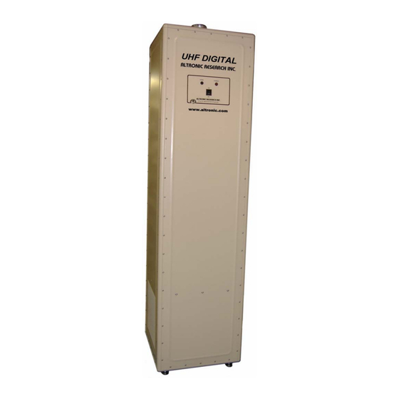
Summary of Contents for Altronic 6715 D
- Page 1 ALTRONIC RESEARCH, INC. P.O. BOX 249, YELLVILLE, ARKANSAS, U.S.A. 72687-0249 PHONE 870-449-4093 FAX 870-449-6000 1-800-482-LOAD (5623) in US altronic.com MODEL 6715 D COAXIAL LOAD RESISTOR...
- Page 2 MODEL 6715D 15 KW DIGITAL UHF AIR COOLED COAXIAL RESISTOR 6715D/Rev. Jul.2020 Page 2 Altronic Research Inc.
-
Page 3: Warranty
The foregoing is the only warranty of Altronic Research Incorporated and is in lieu of all other warranties expressed or implied. -
Page 4: Table Of Contents
3-6 Mounting ..................13 3-7 Connections ................... 13 3-8 Ducting ..................14 3-9 Adjustments ................... 14 Preparation for Reshipment ............14 IV. Theory of Operation 4-1 General ..................15 4-2 Control Circuits ................15 6715D/Rev. Jul.2020 Page 4 Altronic Research Inc. -
Page 5: Section Page
5-1 Cleaning ..................16 5-2 Lubrication ..................16 5-3 RF Circuit ..................16 VI. Diagrams 6-1 Outline and Dimensions ..............17 6-2 Schematic Diagram ................ 18 6-3 Parts List ..................19 VII. Specifications ................... 20 6715D/Rev. Jul.2020 Page 5 Altronic Research Inc. -
Page 6: Warnings And Precautions
NEVER OPERATE WITH INTERLOCK BYPASSED OR MALFUNCTIONING. TO DO SO WILL VOID THE WARRANTY. RF RADIATION HAZARD ALL PANELS, GRILL COVERS AND SCREWS MUST BE PROPERLY INSTALLED AND TIGHT TO AVOID RF RADIATION HAZARD. 6715D/Rev. Jul.2020 Page 6 Altronic Research Inc. - Page 7 CAUTION When using any cleaning solvents or solutions, assure that there is adequate ventilation to protect personnel from breathing any irritable or toxic fumes. 6715D/Rev. Jul.2020 Page 7 Altronic Research Inc.
-
Page 8: Introduction
The blower control circuit consists of three switches wired in parallel to control the blower motor contactor. Power is supplied to this contactor and to the "Blower On" lamp whenever the equipment is attached to the correct power supply and the main power 6715D/Rev. Jul.2020 Page 8 Altronic Research Inc. -
Page 9: Mechanical Description
AC power supply for the unit, will notify the operator of a fault. 1-8. Operating and Adjustment Controls. The only operating control is the main power switch. No field adjustments are necessary or possible. 6715D/Rev. Jul.2020 Page 9 Altronic Research Inc. -
Page 10: Operator Training
The proper procedure to lock out and mark controls prior to allowing or commencing maintenance on the equipment; The proper procedure to obtain clearance to remove lockouts and out-of-service marks and return the equipment to normal service. 6715D/Rev. Jul.2020 Page 10 Altronic Research Inc. -
Page 11: Test Equipment And Special Tools
1 Torx T-20 driver 1 Tee handle hex key, 7/32" bit 1 Power screwdriver with 7/32" hex key & torx T-20 bit 6715D/Rev. Jul.2020 Page 11 Altronic Research Inc. -
Page 12: Preparation For Use And Reshipment
Consideration should be given to adequate accessibility for maintenance and unit replacement. No attempt is made in this handbook to present complete installation instructions, since physical differences in plant will determine the installation procedure. General guidelines are outlined in subsequent paragraphs. 6715D/Rev. Jul.2020 Page 12 Altronic Research Inc. -
Page 13: Location
AC power is supplied to the unit and no overheat condition exists. The normally open terminals are isolated from the normally closed terminals and are provided for an alarm circuit for reject (standby) mode operation or remote installations. 6715D/Rev. Jul.2020 Page 13 Altronic Research Inc. -
Page 14: Ducting
Preparation for Reshipment. No special measures are required to prepare the Model -10. 6715D for reshipment. Care must be taken to protect the RF connector and to immobilize the swivel flange. Packaging should provide protection against abrasion and impact. 6715D/Rev. Jul.2020 Page 14 Altronic Research Inc. -
Page 15: Theory Of Operation
(TB1) terminal 4. Interlock relay terminals 11 & 12 are paralleled and are connected to interlock terminal strip (TB1) terminal 3. This terminal pair will be open when AC power is supplied to the load. 6715D/Rev. Jul.2020 Page 15 Altronic Research Inc. -
Page 16: Maintenance
CAUTION! The resistors are hard, brittle ceramic material. It is very important to avoid impact and excessive force when installing or removing them. 6715D/Rev. Jul.2020 Page 16 Altronic Research Inc. -
Page 17: Outline And Dimensions
SECTION VI 6-1 OUTLINE AND DIMENSIONS 6715D/Rev. Jul.2020 Page 17 Altronic Research Inc. -
Page 18: Schematic Diagram
6-2 SCHEMATIC DIAGRAM 6715D/Rev. Jul.2020 Page 18 Altronic Research Inc. -
Page 19: Parts List
6-3 REPLACEMENT PARTS LIST MODEL 6715D (CONSULT FACTORY) 6715D/Rev. Jul.2020 Page 19 Altronic Research Inc. -
Page 20: Specifications
115 VAC, 60 Hz, 9 Amp., 1 Phase 230 VAC, 50/60 Hz, 3 Amp., 1 Phase Finish ---------------------------------------------------------------------- Beige Splatter Serial No.____________Frequency___________Resistance_________ dBA@3ft < 80dBA Model________________________________Inspected by___________Date________________ CRAFTED WITH PRIDE IN ARKANSAS, U.S.A. 6715D/Rev. Jul.2020 Page 20 Altronic Research Inc.


Need help?
Do you have a question about the 6715 D and is the answer not in the manual?
Questions and answers