Table of Contents
Advertisement
Quick Links
Lightmeter LM10
Summary
1. Introduction.................................................................................................................................. 2
1.1. Commissioning..................................................................................................................... 2
1.2. Device description................................................................................................................3
2. Display......................................................................................................................................... 4
2.1. Measured value displays......................................................................................................4
2.2. Additional information...........................................................................................................4
3. Functions...................................................................................................................................... 5
3.1. Button functions....................................................................................................................5
3.2. Acoustic display.................................................................................................................... 6
3.3. Audio functions..................................................................................................................... 6
3.4. Switching of measurement function......................................................................................7
4. Device settings............................................................................................................................. 8
4.1. Functions of data logger.......................................................................................................8
4.2. Functions of settings.............................................................................................................9
4.3. Settings menu....................................................................................................................... 9
5. Data logger................................................................................................................................. 11
5.1. Continuous measurements.................................................................................................11
5.2. Single-spot measurement...................................................................................................11
5.3. Data set management........................................................................................................ 11
5.4. Transferring data sets.........................................................................................................12
6. Measurement............................................................................................................................. 13
6.1. Preparation for measurement.............................................................................................13
6.2. Measurement of the visible spectrum with the measuring probe VL10...............................13
6.3. Calculation of flicker component.........................................................................................14
6.4. Measuring the flickering rate and flickering frequency........................................................14
6.5. Measurement of the infrared spectrum with the measuring probe IR10.............................16
6.6. Measurement of the ultraviolet spectrum with the measuring probe UV10.........................16
6.7. Measurement of the colour temperature with the measuring probe TF10...........................17
6.8. Signal analysis at the voltage output..................................................................................17
7. Software FM-Data...................................................................................................................... 18
7.1. The program FM-Data........................................................................................................ 18
7.2. Installing FM-Data on Windows 2000/XP...........................................................................18
7.3. Installing FM-Data on Windows Vista/7/8/10......................................................................18
7.4. Installation of the USB-Driver for the Lightmeter LM10 on Windows 2000/XP....................20
7.6. Running FM-Data............................................................................................................... 23
7.7. Transferring and Displaying Datasets.................................................................................24
7.8. Graph and report................................................................................................................ 25
7.9. Cutting down datasets........................................................................................................ 27
7.10. Print and Export................................................................................................................ 27
7.11. Modifying of the instrument settings of the LM10L............................................................28
7.12. Help Function.................................................................................................................... 28
8. Appendix.................................................................................................................................... 29
8.1. Power supply...................................................................................................................... 29
8.2. Maintenance....................................................................................................................... 29
8.3. Firmware............................................................................................................................. 29
8.4. Technical information.......................................................................................................... 30
8.5. Description of the pin assignment of the output voltage Lightmeter LM10S/LS..................31
8.6. Scope of Delivery................................................................................................................ 31
8.7. Disposal.............................................................................................................................. 32
This manual refers to LM10-Firmware 1.09 and FM-Data program version 2.2.0.0.
The current version of the manual is available on the homepage www.fauser.biz.
Technical changes reserved; we do not accept liability for any errors.
1
Advertisement
Table of Contents

Related Manuals for Fauser Elektrotechnik Lightmeter LM10

Summary of Contents for Fauser Elektrotechnik Lightmeter LM10
-
Page 1: Table Of Contents
7.2. Installing FM-Data on Windows 2000/XP................18 7.3. Installing FM-Data on Windows Vista/7/8/10..............18 7.4. Installation of the USB-Driver for the Lightmeter LM10 on Windows 2000/XP....20 7.5. Installation of the USB-Driver for the Lightmeter LM10 on Windows Vista/7/8/10....21 7.6. Running FM-Data....................... 23 7.7. -
Page 2: Introduction
Lightmeter LM10 1. Introduction The Lightmeter LM10 is an innovative new development for checking the quality of light sources. For this, the parameters such as illumination intensity, flicker frequency and flicker rate are measured. Moreover, the flickering of lamp can be illustrated acoustically in audible as well as ultrasonic range via a loudspeaker. -
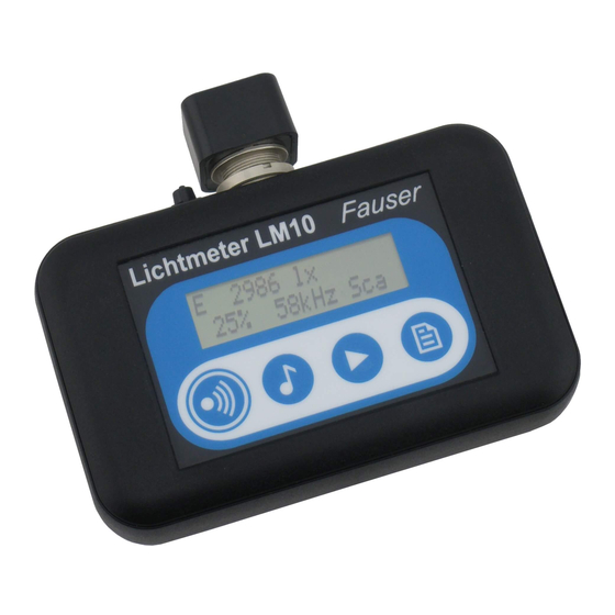
Page 3: Device Description
Lightmeter LM10 1.2. Device description Figure 1: Lightmeter LM10 ➊ Display (→ 2) ➋ On/Sound button (→ 3.1) ➌ Audio/USB button (→ 3.1) ➍ Selection/Menu button (→ 3.1) ➎ Record button (→ 3.1) ➏ USB port (only LM10L/LS) For connecting the Lightmeter FM10L/LS with a PC and for power supply with the USB-power supply (Art.-No. -
Page 4: Display
Lightmeter LM10 2. Display The Lightmeter LM10 has a two-line display for presenting measured values, functions and setting menu. The software version is displayed when switched on 2.1. Measured value displays In the standard display, the illumination intensity in Lux and active recording of a data record is visible in the first line. -
Page 5: Functions
Lightmeter LM10 3. Functions 3.1. Button functions The four buttons have double functions; the main functions can be called up promptly in the measuring mode. The buttons help in navigation in menu mode. All the button functions are speci- fied in table 1. -
Page 6: Acoustic Display
The func- tion is displayed by the symbol 3.3. Audio functions The Lightmeter LM10 has three audio functions to show the flickering of lamps acoustically. The various audio modes can be selected by pressing the Audio button. Scan mode Shows the flicker rate in % and the dominant flicker frequency in kHz. -
Page 7: Switching Of Measurement Function
Lightmeter LM10 in the audible range. If no dominant frequency is available in the range between 10 kHz and 400 kHz, the starting frequency 10 kHz is reproduced. The scan process can be repeated by pressing the Selection button. The dominant flicker frequency is displayed, ″USa″ appears on display in this mode. -
Page 8: Device Settings
Lightmeter LM10 4. Device settings Here all the setting options of the Lightmeter LM10 are described, the functions of the data logger are available only in the versions LM10L/LS. The logger settings and device settings can be made directly on LM10 using the settings menu (→... -
Page 9: Functions Of Settings
4.3. Settings menu When the Selection/Menu button is pressed for two seconds, the Lightmeter LM10 is in menu mode. Here logger settings as well as device settings can be adjusted. For navigation use the buttons as shown in table 1. - Page 10 Lightmeter LM10 Menu → Data logger → Data memory → Display → Data record Delete Logger mode → Continuous measurement Single-spot Sample interval 0,25 seconds → 1 second 10 seconds 1 minute USB-Transfer → langsam schnell Settings → Threshold value % →...
-
Page 11: Data Logger
Lightmeter LM10 5. Data logger The data logger of the Lightmeter LM10L/LS has two operating modes. These modes can be selected in the device settings under Data logger→Logger mode. 5.1. Continuous measurements In continuous mode the measured values are recorded with the specified measurement interval. -
Page 12: Transferring Data Sets
Lightmeter LM10 5.4. Transferring data sets By pressing the Audio/USB button for two seconds, the LM10L/LS switches to the USB mode and in display appears: ″USB mode: Waiting for PC″. Now the communication between the Lightmeter LM10L/LS and the PC is possible through the USB cable. -
Page 13: Measurement
6. Measurement 6.1. Preparation for measurement Insert the measuring probe, required for measuring, in the sensor connector of Lightmeter LM10. The measuring probe can also be connected to LM10 via 80 cm long connecting cable. Select the corresponding measurement function via the Selection button. -
Page 14: Calculation Of Flicker Component
Lightmeter LM10 6.3. Calculation of flicker component LM10 calculates the flicker component according to the following selectible procedures: Ripple content: Φmax – Φmin ∗100% Φmax In accordance with the Standard of Building Biology Testing Methods SBM-2015. Flicker%: Φmax – Φmin ∗100 %... - Page 15 Lightmeter LM10 In case of incandescent lamps and halogen lamps, the flicker frequency is always 100 Hz and the flickering rate is from 15% to 25%. Low-volt halogen lamps with electronic power supply are an exception. Brightness of a compact fluorescent lamp (Flicker rate 31%, flicker frequency 49 Hz) Compact fluorescent lamps also known as energy-saving lamps have a flicker frequency in the range from approx.
-
Page 16: Measurement Of The Infrared Spectrum With The Measuring Probe Ir10
Lightmeter LM10 6.5. Measurement of the infrared spectrum with the measuring probe IR10 With the measuring probe IR10 (Article no. 263), the infrared spectrum can be measured in the range (λ ) from 790 nm to 1050 nm. The unit is W/m². Select the IR unit for the infrared range using the Selection button. -
Page 17: Measurement Of The Colour Temperature With The Measuring Probe Tf10
Lightmeter LM10 6.7. Measurement of the colour temperature with the measuring probe TF10 For this, the measuring probe TF (Article no. 266) must be used and the Tf unit for the colour temperature must be selected using the selection button. -
Page 18: Software Fm-Data
CD FM-Data and follow the instructions of the installation program. After the installation, open the windows explorer and choose the folder C:\programme(x86) \Fauser Elektrotechnik\FM-Data. Right-click on the application FM-Data and choose the menu point attributes. Now select compatibility. - Page 19 Lightmeter LM10 Activate authorisation level: Execute program as administrator.
-
Page 20: Installation Of The Usb-Driver For The Lightmeter Lm10 On Windows 2000/Xp
Lightmeter LM10 7.4. Installation of the USB-Driver for the Lightmeter LM10 on Windows 2000/XP Connect the Lightmeter LM10L to your PC via the USB-cable. Turn on the LM10L and acti- vate USB-mode (→ 3.1). The window of the hardware assistant appears on the screen. -
Page 21: Installation Of The Usb-Driver For The Lightmeter Lm10 On Windows Vista/7/8/10
Now, the USB-driver is installed and the program FM-Data is ready for use 7.5. Installation of the USB-Driver for the Lightmeter LM10 on Windows Vista/7/8/10 Connect the Lightmeter LM10L to your PC via the USB-cable. Turn on the LM10L and acti- vate USB-mode (→... - Page 22 Lightmeter LM10 The following message appears: Insert the storage for ″Fieldmeter FM10″. If the software CD FM-Data is not in the drive, insert it. Now, the USB-driver of the Lightmeter LM10 is installed. If the message USB Cummunication Error appears when loading datasets, the computer...
-
Page 23: Running Fm-Data
Lightmeter LM10 7.6. Running FM-Data After the installation, you can start FM-Data via the taskbar using Start/Programmes/FM-Data or via the programme-icon on the desktop. While the application is loading a starting screen appears which shows the version number of the software. -
Page 24: Transferring And Displaying Datasets
Lightmeter LM10 7.7. Transferring and Displaying Datasets In order to load the recorded measurement data from the Lightmeter LM10 to the PC, you connect the LM10L with the bundled USB-cable with one of the PC’s USB-slots. Turn on the LM10L and switch to the USB-mode by pressing the Audio/USB button for two seconds;... -
Page 25: Graph And Report
Lightmeter LM10 7.8. Graph and report After loading the dataset of a long-term measurement the graphic window related to the dataset opens. On the right side in the top grey field, the most important information like the name of the dataset, starting and ending time of the record, the measurement interval and the used probe are shown. - Page 26 Lightmeter LM10 If the dataset of a single-spot measurement is opened, the measurement values are shown in a bar chart. The comment window to tag the separate measurement values opens through double- clicking with the left mouse button. The other functions of the graphic window are similar to those...
-
Page 27: Cutting Down Datasets
Lightmeter LM10 7.9. Cutting down datasets Using the Edit/Crop function a time frame of a data set can be cut and saved. To do this, the time frame to be cut is marked by keeping the left mouse button pressed, the start and end time of the marked frame is displayed using the diagram in red bordered window. -
Page 28: Modifying Of The Instrument Settings Of The Lm10L
Lightmeter LM10 7.11. Modifying of the instrument settings of the LM10L The logger settings and the basic settings of the Lightmeter LM10L can be regarded in the menu mode of the Lightmeter LM10L and with the software FM-Data. To view and to edit the settings with FM-Data, the LM10L is connected to the PC, and it is swit - ched to the USB-mode by pressing the Audio/USB-button for two seconds. -
Page 29: Appendix
8. Appendix 8.1. Power supply The Lightmeter LM10 is provided with two batteries of type Mignon AA with voltage. The battery compartment is located at the bottom side of LM10. Batteries of type NiMH are recommended for frequent use of Lightmeter LM10. In accordance with Art.-No. -
Page 30: Technical Information
Lightmeter LM10 8.4. Technical information Measurement range Illumination intensity E 20000 lx Infrared spectrum 200,00 W/m² Ultraviolet spectrum 20000 mW/m² Flicker rate 0...100 % Calculation type Ripple content according to SBM-2015 Flicker% according to IESNA Flicker frequency 50 Hz...400 kHz... -
Page 31: Description Of The Pin Assignment Of The Output Voltage Lightmeter Lm10S/Ls
Control output (Autorange) Figure 3: Pin assignment Lightmeter LM10S/LS 8.6. Scope of Delivery Scope of delivery Lightmeter LM10 Art.-No. 250 Lightmeter LM10, measuring probe VL10 for visible spectrum, extension cable, manual, batte- ries, transport case Scope of delivery Lightmeter LM10S Art.-No. 251... -
Page 32: Disposal
Lightmeter LM10 8.7. Disposal This product bears the recycling symbol according to EU Directive 2002/96/EC. This means that the device has to be returned to the manufacturer in order for recycling. A disposal with the resi- dual waste is not allowed.
Need help?
Do you have a question about the Lightmeter LM10 and is the answer not in the manual?
Questions and answers