
Related Manuals for adafruit learning system ItsyBitsy 32u4


Summary of Contents for adafruit learning system ItsyBitsy 32u4
- Page 1 Introducing ItsyBitsy 32u4 Created by lady ada Last updated on 2018-08-22 04:04:57 PM UTC...
-
Page 2: Table Of Contents
Guide Contents Guide Contents Overview Pinouts Which do you have? Power Pins Adafruit LiIon/LiPoly Backpack Add-On for Pro Trinket/ItsyBitsy 5V Power Pins 3V Power Pins Logic pins Other Pins! Arduino IDE Setup https://adafruit.github.io/arduino-board-index/package_adafruit_index.json Using with Arduino IDE Install Drivers (Windows Only) Blink Manually bootloading Ubuntu &... -
Page 3: Overview
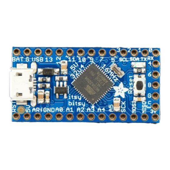
ItsyBitsy 32u4 is only 1.4" long by 0.7" wide, but has 6 power pins, 6 analog & digital pins and 17 digital pins. It packs much of the same capability as an Arduino UNO. - Page 4 The ItsyBitsy 32u4 uses the Atmega32u4 chip, which is the same core chip in the Arduino Leonardo as well as the same chip we use in our Feather 32u4. The 5V 16 MHz It runs at the same speed and voltage of an Arduino UNO or Leonardo.
- Page 5 polarity protection, thermal and current-limit protection. Low current 3.3V regulator output from chip, for small sensors For the 3V version: We have two special pins on the 3V version of this board. There's a VHigh pin, this pin is a power pin whose voltage is the higher of VBAT and VUSB.
-
Page 6: Pinouts
Pinouts The ItsyBitsy 32u4's come in two flavors - 5V and 3V. The pinouts for these are very similar except for the power pins which have different voltages! © Adafruit Industries https://learn.adafruit.com/introducting-itsy-bitsy-32u4 Page 6 of 22... -
Page 7: Which Do You Have
3V 8MHz or 32u4 5V 16 MHz Power Pins Both ItsyBitsy 32u4's have BAT G USB on the top left, right next to the micro USB port These pins are: BAT - battery input for an alternative power source to USB. -
Page 8: Adafruit Liion/Lipoly Backpack Add-On For Pro Trinket/Itsybitsy
On the 3V Itsy, we have a different regulator, so the voltage can only be from 3.5V to 6VDC GND - Power/data ground USB - This is the same pin as the MicroUSB connector's 5V USB power pin. This should be used as an output to get 5V power from the USB port. -
Page 9: 3V Power Pins
G - these are all Ground pins 3V Power Pins In addition to the three standard power pins, the 3V ItsyBitsy has a few more pins available for power sourcing: 3V - this is the regulated output from the onboard regulator. You can draw 500mA whether powered by USB or battery. -
Page 10: Other Pins
#11 - GPIO #11, can do PWM output. #12 - GPIO #12, also analog input A11 #13 - GPIO #13, can do PWM output and is connected to the red LED next to the Reset button Along the left edge A0 thru A5 - These are each analog input as well as digital I/O pins. -
Page 11: Arduino Ide Setup
Arduino IDE Setup The first thing you will need to do is to download the latest release of the Arduino IDE. You will need to be using version 1.8 or higher for this guide https://adafru.it/f1P https://adafru.it/f1P After you have downloaded and installed the latest version of Arduino IDE, you will need to start the IDE and navigate to the Preferences menu. -
Page 12: Https://Adafruit.github.io/Arduino-Board-Index/Package_Adafruit_Index.json
We will be adding a URL to the new Additional Boards Manager URLs option. The list of URLs is comma separated, and you will only have to add each URL once. New Adafruit boards and updates to existing boards will automatically be picked up by the Board Manager each time it is opened. - Page 13 Here's a short description of each of the Adafruit supplied packages that will be available in the Board Manager when you add the URL: Adafruit AVR Boards - Includes support for Flora, Gemma, Feather 32u4, Trinket, & Trinket Pro. Adafruit SAMD Boards - Includes support for Feather M0 and M4, Metro M0 and M4, ItsyBitsy M0 and M4, Circuit Playground Express, Gemma M0 and Trinket M0 Arduino Leonardo &...
-
Page 14: Using With Arduino Ide
Using with Arduino IDE Since the ItsyBitsy 32u4 uses an ATmega32u4 chip running at 8 or 16 MHz, you can pretty easily get it working with the Arduino IDE. Many libraries (including the popular ones like NeoPixels and display) work great with the '32u4 and 8/16 MHz clock speed. -
Page 15: Install Drivers (Windows Only)
Install Drivers (Windows Only) When you plug in the Feather, you'll need to possibly install a driver Click below to download our Driver Installer https://adafru.it/AB0 https://adafru.it/AB0 Download and run the installer Run the installer! Since we bundle the SiLabs and FTDI drivers as well, you'll need to click through the license ©... -
Page 16: Blink
Select which drivers you want to install: Click Install to do the installin' Blink Now you can upload your first blink sketch! © Adafruit Industries https://learn.adafruit.com/introducting-itsy-bitsy-32u4 Page 16 of 22... - Page 17 Plug in the ItsyBitsy 32u4 and wait for it to be recognized by the OS (just takes a few seconds). It will create a serial/COM port, you can now select it from the dropdown! Now load up the Blink example ©...
-
Page 18: Manually Bootloading
// the setup function runs once when you press reset or power the board void setup() { // initialize digital pin 13 as an output. pinMode(13, OUTPUT); // the loop function runs over and over again forever void loop() { digitalWrite(13, HIGH);... - Page 19 made to configure modem manager not to touch the board and will fix the programming difficulty issue. Follow the steps for installing Adafruit's udev rules on this page. (https://adafru.it/iOE) © Adafruit Industries https://learn.adafruit.com/introducting-itsy-bitsy-32u4 Page 19 of 22...
-
Page 20: Downloads
Downloads Files EagleCAD files for both 3V and 5V 32u4 ItsyBitsy's (https://adafru.it/BkS) Fritzing files for both types in the Adafruit Fritzing library (https://adafru.it/aP3) Bootloaders https://adafru.it/Apx https://adafru.it/Apx https://adafru.it/Apy https://adafru.it/Apy ItsyBitsy 3V Schematic & Fabrication print The 3.3V schematic regulator should be AP2112K-3.3 ©... -
Page 21: Itsybitsy 5V
ItsyBitsy 5V Schematic & Fabrication print © Adafruit Industries https://learn.adafruit.com/introducting-itsy-bitsy-32u4 Page 21 of 22... - Page 22 © Adafruit Industries Last Updated: 2018-08-22 04:04:52 PM UTC Page 22 of 22...
Need help?
Do you have a question about the ItsyBitsy 32u4 and is the answer not in the manual?
Questions and answers