
Related Manuals for RONK VIGILANT Series


Summary of Contents for RONK VIGILANT Series
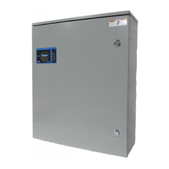
- Page 1 ELECTRICAL INDUSTRIES, INC. 100 & 200 AMP OWNER’S & INSTALLATION MANUAL MODEL # VTS01001240SX/VTS02001240SX...
- Page 2 No part of this publication may be reproduced or used in any form by any means – graphic, electronic or mechanical, including photocopying, recording, taping or information storage and retrieval systems – without the written permission of Ronk Electrical Industries, Inc.
-
Page 3: Table Of Contents
Controller test switch ............................18 Remote test switch ............................18 Exerciser ................................18 MANUAL TRANSFER ........................19 Manual Transfer of Mechanism ............................19 100A/200A Manual Transfer ............................19 MAINTENANCE ..........................20 Recommended Maintenance ............................20 Maintenance..................................20 Ronk Vigilant Owner’s and Installation Manual ®... - Page 4 ON/AUTO/OFF Mode ..............................23 WARRANTY ..........................24 Vigilant Owner Warranty Policy ............................24 ® Limited Warranty ..............................24 Warranty Period ................................ 24 Warranty Registration Process ..........................24 About Our Warranty ..............................24 NOTES ............................. 25 Ronk Vigilant Owner’s and Installation Manual ®...
-
Page 5: Introduction
INTRODUCTION Contact Information Thank you for your purchase of a Ronk Vigilant Series Automatic ® Transfer Switch (ATS). This product is designed for use with standby There are several ways to contact us for answers to questions you generators. This ATS may have different installation requirements may have about your product. -
Page 6: Safety
You must also make sure that the procedure, work method or operating technique that you choose does not render the equipment unsafe. Ronk Vigilant Owner’s and Installation Manual ®... -
Page 7: Safety Labels
National Electrical • If you have questions about intended use, contact Code (NEC) (Article 701 Legally Required Standby Systems Ronk Electrical Industries, Inc. or Article 702 Optional Standby Systems, as applicable), and Occupational Safety and Health Administration (OSHA), •... -
Page 8: Specifications
200A/Enclosure – 24 x 20 x 6 in. (61.0 x 50.8 x 15.2 cm) - 240/480 Weight 100A - 29 lb (11.3 kg), 200A - 58 lb (23.1 kg) One of the connected L-N phases must be below the under-voltage threshold to initiate transfer sequence. Ronk Vigilant Owner’s and Installation Manual ®... -
Page 9: Vigilant ® Product Series
If any missing parts or damage is discovered when unpacking, do not return the unit to the place of purchase; please contact Ronk Electrical for instructions on how to proceed. Never install a switch that has been damaged. -
Page 10: Vigilant ® Catalog Number Identification
VIGILANT PRODUCT SERIES ® Vigilant Catalog Number Identification ® Figure 3 Figure 4 Ronk Vigilant Owner’s and Installation Manual ®... -
Page 11: Installation And Wiring
• Never install the switch where any corrosive substance may come in contact with the enclosure. • Protect the switch at all times against excessive moisture, dust, dirt, lint, construction grit and corrosive vapors. Ronk Vigilant Owner’s and Installation Manual ®... -
Page 12: Power Connections
Wire size range 250 kcmil-6 AWG copper or aluminum using Ilsco lug # CA6-RP Figure 5 – Power Cable Connection Locations WARNING Always install the transparent protective shields covering the power connections of the switch mechanism once the proper connections are performed. Ronk Vigilant Owner’s and Installation Manual ®... -
Page 13: Connections
AC sensing, which it obtains from the distribution system via Battery -. RSC1 and RSC2 need to be connected to the remote start/stop connections of the generator to allow automatic starting. These are N.O. dry contacts. Ronk Vigilant Owner’s and Installation Manual ®... -
Page 14: General Operation
(TDNE) has expired before switching to the generator position. All connected loads will be transferred to the generator power source. Ronk Vigilant Owner’s and Installation Manual ®... -
Page 15: Adjustments And Settings
Pots Jumper Jumper Location as illustrated. LED Annuciator Jumper Jumper Installing jumpers in the 12/24 VDC jumper locations for 24VDC system operation may damage the control board. Figure 9 – 12/24 VDC Operation Ronk Vigilant Owner’s and Installation Manual ®... -
Page 16: System Adjustments
17% v 16% v 15% v 14% v 13% Pickup v voltage Pickup v Pickup v Pickup v Pickup v Pickup v Pickup v Pickup v setting Set the over/under frequency setting Ronk Vigilant Owner’s and Installation Manual ®... -
Page 17: Timing Adjustments
Time Delay Emergency (Generator) to Normal (utility): This delay allows the utility source to be monitored for stability. This emergency (generator) to normal (utility) time delay allows the utility to be monitored for the set amount of time to confirm that it is fully restored and stable Ronk Vigilant Owner’s and Installation Manual... -
Page 18: Testing Adjustments
The exerciser can perform a test for a load or no-load condition. For details instructions on operational and setting instructions, see ENGINE EXERCISER AND EXTERNAL LED ANNUNCIATION on page 22. Ronk Vigilant Owner’s and Installation Manual ®... -
Page 19: Manual Transfer
WARNING Figure 12 – Manual Transfer Lever Location Never allow the removable lever handle to come in contact with live wires or terminals. Ronk Vigilant Owner’s and Installation Manual ®... -
Page 20: Maintenance
Once a year, have a licensed electrician clean the inside of the switch and inspect for: • Damage or loose parts • Discoloration of wire insulation or components Ronk Vigilant Owner’s and Installation Manual ®... -
Page 21: Drawings
VIGILANT 100A / 200A ATS 2000 SERIES TITLE: WIRING DIAGRAM 2 POLE 240V CUSTOMER: DRAWING NO: REVISIONS: 12/22/14 NEW (ECO #031024) DEF E DRAWN 2/2/15 CONSOLIDATED TERMINATIONS FOR NEW VENDOR SCALE CHECKED E.B. DATE 12/22/14 APPROVED Ronk Vigilant Owner’s and Installation Manual ®... -
Page 22: Exerciser
The following sections will explain how to: 1. Set curent time and date 2. Set program timing 3. Review your program 4. ON/AUTO/OFF mode Figure 15 Figure 13 Ronk Vigilant Owner’s and Installation Manual ®... -
Page 23: Clearing The Exerciser
The time of day is displayed in the 24-hour The internal battery current draw would not be applicable when an notation, so 00:00 is midnight. energized utility source is supplying power to the switch. Ronk Vigilant Owner’s and Installation Manual ®... -
Page 24: Warranty
LIMITED WARRANTY occurred because of misuse, lack of routine maintenance, Ronk Electrical Industries, Inc. will repair or replace, free of shipping, handling, warehousing, or improper installation. charge, any part(s) of the equipment that is defective in material or... -
Page 25: Notes
NOTES Ronk Vigilant Owner’s and Installation Manual ®... - Page 26 NOTES Ronk Vigilant Owner’s and Installation Manual ®...
- Page 27 NOTES Ronk Vigilant Owner’s and Installation Manual ®...
- Page 28 RONK | PO Box 160, 106 East State Street, Nokomis, IL 62075-0160 | Toll-Free: 800-221-7665 | ronkelectrical.com UG-001-02 1-2020...
Need help?
Do you have a question about the VIGILANT Series and is the answer not in the manual?
Questions and answers