Advertisement
Quick Links
Advertisement

Related Manuals for AXM Paper Space Scale Models STS 51-L


Summary of Contents for AXM Paper Space Scale Models STS 51-L
- Page 1 © 2007 Assembly Instructions for STS 51-L payload (Challenger’s last flight)
- Page 2 The aft payload frame is displayed in The forward payload frame needs to be this photo with the circular sections cut folded to make the shape as the photo. open. All boxes are glued to areas indicated.
- Page 3 Building the IUS (inertial upper stage) is very straightforward. Follow the sequence and glue the correspondent parts as photo shows. Hexagonal box: The cover with numbers 1 and 2 is glued on top of the hexagonal box with number 1 pointing to the seam of the box.
- Page 4 Cones 1 and 2 are glued on top of box with correspondent numbers. Part 3 is glued to the side as shown. The TDRS satellite (Tracking and Data Release System) is complete. The TDRS stack is glued on top of the IUS with the flat white/black panel to the right and the circular antennae to the left as photo shows.
- Page 5 The photos below show the sequence to build the solar panels of the TDRS.
- Page 6 The completed panel stack slides on top of the TDRS satellite. These are the pins that will be glued on the payload bay so the Aft payload frame will rotate. Insert the pins in the side openings of the Aft payload frame.
- Page 7 Building the MPESS structure: Easy to assemble. Fold to shape as photo shows and glue on bay 3 in the payload bay. Glue white panel on top of the MPESS structure. This panel will hold the Spartan-Halley craft.
- Page 8 Building Spartan-Halley craft: These are parts A, B, C. Second photo to the right shows parts A and B glued. Left bottom photo shows all parts assembled on top of box C. Note position of Spartan-Halley on top of the MPESS structure. Parts D and E are shown here.
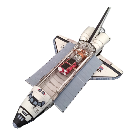
- Page 9 Note location of KU-band antenna that is glued on the tab from the right payload bay door. Glue the remote manipulator arm at the end after installing all elements. Overview of the payload bay http://www.axmpaperspacescalemodels.com...
Need help?
Do you have a question about the STS 51-L and is the answer not in the manual?
Questions and answers