Table of Contents
Advertisement
Available languages
Available languages
Quick Links
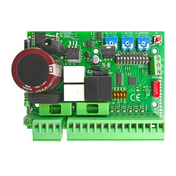
• Centrale bassa tensione per un motore 12/24 Vdc
• Cancelli scorrevoli, porte basculanti, serrande
• Possibilità collegamento encoder
START-S7LT
Ingresso BASSA TENSIONE
Ingresso BASSA TENSIONE
Alimentazione Accessori (max 1,6 A)
Alimentazione Accessori (max 1,6 A)
Contatto pulito per lampeggiante
Contatto pulito per lampeggiante
Contatto pulito per serratura o luce di cortesia
Contatto pulito per serratura o luce di cortesia
- Antenna / Comune servizi e sicurezze
+ 5Vdc alimentazione ENCODER
- alimentazione ENCODER
-1-
-2-
Motore
-3-
Motore
-4-
-5-
-6-
-7-
-8-
-9-
-10-
-11-
STOP
-12-
FOTO ch
-13-
FCA
-14-
FCC
-15-
START
-16-
CHIUDE
-17-
-18-
+ Antenna
-19-
-20-
Segnale ENCODER
-21-
RoHS
C O M P L I A N T
2002/95/EC
Istruzioni e avvertenze per l'installatore
MOT 1
Lampeggiante
12/24 Vac/dc
N.A.
N.A.
N.C.
N.C.
+ BAT
Fastom per collegamento batteria
- BAT
*
Alimentazione fotocellule:
Mosertti 5-6
Assorbimento Max 1.6 A
*
Fotocellule
attive sulla
*
chiusura
N.C.
Advertisement
Chapters
Table of Contents

Related Manuals for nologo START-S7LT


Summary of Contents for nologo START-S7LT
- Page 1 • Centrale bassa tensione per un motore 12/24 Vdc • Cancelli scorrevoli, porte basculanti, serrande • Possibilità collegamento encoder START-S7LT Istruzioni e avvertenze per l’installatore Ingresso BASSA TENSIONE Ingresso BASSA TENSIONE Motore Motore MOT 1 Alimentazione Accessori (max 1,6 A)
-
Page 2: Table Of Contents
START-S7LT Manuale tecnico Indice capitoli Premessa Questo manuale fornisce tutte le informazioni speci- Par. Descrizione Pag. fiche necessarie alla conoscenza ed al corretto uti- Introduzione lizzo dell’apparecchiatura in Vostro possesso. Precauzioni di sicurezza Esso deve essere letto attentamente all’atto dell’ac- Simbologia e avvertenze quisto dello strumento e consultato ogni volta che Sistemi di sicurezza sorgano dubbi circa l’utilizzo o ci si accinga ad effet-... -
Page 3: Introduzione
START-S7LT Manuale tecnico Introduzione Precauzioni di sicurezza In caso di utilizzo scorretto, di riparazioni o modifiche apportate personalmente decade qualsiasi garanzia. Il produttore declina ogni responsabilità per i danni derivanti da un utilizzo non appropriato del prodotto o da utilizzo diverso da quello per cui il prodotto è stato creato. Il produttore declina ogni responsabilità per danni consequenziali ad eccezione della responsabilità... -
Page 4: Descrizione Prodotto
Manuale tecnico Descrizione Prodotto La START-S7LT è una scheda elettronica di nuova generazione con conteggio digitale dei tempi e dei ral- lentamenti. E’ stata realizzata per soddisfare molteplici esigenze: per cancelli scorrevoli, sistemi basculanti e serrande. Le ridotte dimensioni permettono il suo utilizzo anche all’interno di tutti i motori che prevedono l’elet- tronica interna. -
Page 5: Premesse
START-S7LT Manuale tecnico Premesse 3.1 Verifiche preliminari E’ fondamentale fare una scelta corretta nell’installazione della centrale per una adeguata sicurezza e una buona protezione agli agenti atmosferici. Ricordiamo che la centrale contiene parti sottoposte a tensione di rete e componenti elettronici che per loro stessa natura sono sensibili alle infiltrazione e all’umidità. La centrale viene fornita in un contenitore che se adeguatamente installato garantisce un grado di protezione IP55. Installare la centrale su una superficie irremovibile, perfettamente piana ed adeguatamente protetta da... -
Page 6: Installazione Della Centrale
START-S7LT Manuale tecnico Installazione della centrale Schema della centrale e dei collegamenti elettrici collegare batteria utilizzare l’apposito cavo rispettando la po- + BAT larità. NON COLLEGARE J12V D I R E T TA M E N T E LA BATTERIA. -
Page 7: Descrizione Collegamenti Elettrici
START-S7LT Manuale tecnico Descrizione collegamenti elettrici 12/24 Vac/dc Ingresso BASSA TENSIONE: impostazione su JUMPER J12 Motore Uscita per collegamento MOTORE - 12/24 Vdc Uscita per alimentazione accessori: Assorbimento max 1,6 A + 12/24 Vdc c.p. Lamp Contatto pulito per LAMPEggIANTE c.p. -
Page 8: Collegamento Alimentazione E Batteria
START-S7LT Manuale tecnico Collegamento ALIMENTAZIONE e BATTERIA La seguente centralina può esse- Per collegare la batteria utilizzare re alimentata a 12/24 Vac/dc. Per l’apposito cavo rispettando la po- impostare la tensione di alimenta- larità. NON COLLEGARE DIRETTA- zione posizionare il JUMPER 12V M ENTE LA BATTERIA. -
Page 9: Collegamento Luce Di Cortesia
START-S7LT Manuale tecnico Collegamento LUCE di CORTESIA Impostando il DIP 8 in ON, è possibile collegare la luce di cortesia, che rimarrà accesa dall’inizio dell’apertura fino a 2 minuti dopo la chiusura. DIP 8 - ON gRUPPO LUCE Inoltre il secondo canale del TX non co- manda più... -
Page 10: Collegamento Dei Finecorsa Fca Fcc
START-S7LT Manuale tecnico 4.12 Collegamento dei FINECORSA FCA e FCC Nella figura viene mostrato il collegamento di entrambe i finecorsa: Se gli ingressi FCA o FCC non vengono utilizzati, porre in ON DIP 3B per FCA porre in ON DIP 4B per FCC I contatti dei finecorsa devono essere di tipo N.C. -
Page 11: Collegamento Comando Di Start
START-S7LT Manuale tecnico 4.14 Collegamento dei comandi di “START” Il collegamento del comando di apertura START può es- sere effettuato a qualsiasi pulsante o contatto di tipo N.A. (normalmente aperto), collegando il contatto ai morsetti 15- 17. Se vi sono più dispositivi, vanno collegati in parallelo. -
Page 13: Modi Di Funzionamento
Manuale tecnico Modi di funzionamento La centrale START-S7LT è adatta anche per il funzionamento di porte automatiche. Vediamo ora come è possibile impostare l’apparecchiatura per un corretto funzionamento. Per prima cosa notiamo quali sono le differenze tra il funzionamento NORMALE e il funzionamento per PORTE AUTOMATICHE:... -
Page 14: Logica Di Funzionamento Nel Dip A
START-S7LT Manuale tecnico Logica di funzionamento nel DIP A La centrale dispone di una serie di microinterruttori che permettono di attivare varie funzioni al fine di rendere l’impianto più adatto alle esigenze dell’utilizzatore e per la sua maggior sicurezza. Per scegliere la funzione, agire come raffigurato nei microinterruttori 1 e 2 del DIP A Ad ogni comando inverte: apre-chiude. Richiude 1-OFF 2-OFF automatico automaticamente al termine del tempo di pausa. -
Page 15: Fca
START-S7LT Manuale tecnico abilita Posizionare in ON per abilitare l’ingresso 7-ON ingresso ENCODER. Nel caso non si collegasse, encoder impostare su OFF. E’ possibile collegare la luce di cortesia, che ri- marrà accesa dall’inizio dell’apertura fino a 2 mi- 8 - ON luce di cortesia nuti dopo la chiusura. Inoltre, il secondo canale del TX non comanda più... -
Page 16: Gestione Telecomandi Dip9 Off
START-S7LT Manuale tecnico Gestione TELECOMANDI DIP9 OFF Per gestire i telecomandi, la scheda elettronica deve essere provvista di modulo radio. La scheda elettronica è in grado di gestire diversi tipi di codice, il primo telecomando appreso ne determinerà il tipo, di conseguenza, non si possono apprendere telecomandi con tipo di codice differente dal primo telecomando appreso. -
Page 17: Apprendimento Codici
START-S7LT Manuale tecnico Apprendimento dei codici La centrale dispone di un PULSANTE P1 per la programmazione dei tempi e per l’apprendimento dei codici dei radiocomandi. Se per l’apprendimento si utilizza un radiocomando vergine a codice fisso tipo lo SMILE-C, assicurarsi che abbia un codice su tutti i pulsanti, altrimenti provvedere con l’autogenerazione del codice. Nel caso si volesse apprendere un radiocomando rolling-code tipo SMILE-H è... -
Page 18: Accensione E Programmazione
START-S7LT Manuale tecnico Accensione e programmazione All’ accensione della scheda elettronica, se tutto è stato collegato nel modo giusto, il led L1 rosso di segnalazio- ne deve lampeggiare, mentre i led degli ingressi STOP, FOTO, FCA, FCC, ALT COSTA devono essere accesi (se il cancello è... - Page 19 START-S7LT Manuale tecnico Apprendimento tempi con il COMADO DI APERTURA “START” SE NON SI UTILIZZA UN ENCODER: effettuare l’apprendimento con i trimmer di velocità già impostati correttamente. Togliere alimentazione alla centrale Porre in ON l’interruttore DIP 9 L’automazione è in posizione di CHIUSO Alimentare la centrale.
- Page 20 START-S7LT Manuale tecnico Utilizzo dell’ingresso CHIUDE come COMADO DI PEDONALE Nel caso si voglia utilizzare l’ingresso CHIUDE come COMANDO PEDONALE, seguire i seguenti passaggi: Togliere alimentazione alla centrale L’automazione è in Porre in ON l’interruttore DIP 9 posizione di CHIUSO Alimentare la centrale.
-
Page 21: Aumentare Il Tempo Di Pausa
START-S7LT Manuale tecnico Aumentare il tempo di PAUSA E’ possibile aumentare il tempo pausa senza dover ripetere l’operazione di apprendimento tempi. Mentre l’automazione è ferma in pausa, ad ogni pressione del pulsante P1, il tempo di pausa viene incrementato di 5 secondi. -
Page 22: Dichiarazione Ce Di Conformità
START-S7LT Manuale tecnico Dichiarazione CE di conformità (secondo Direttiva 2006/42/CE, Allegato II, parte B) Azienda: EB TECHNOLOGY SRL Indirizzo: Corso Sempione 172/5 Il sottoscritto Ernestino Bandera, 21052 Busto Arsizio VA Italia Amministratore Nome prodotto: START-S7LT centrale elettronica di comando DICHIARA CHE: per 1 motori 12/24 Vdc IL PRODOTTO E’... - Page 23 DICHIARAZIONE DI CONFORMITA’ DECLARATION OF CONFORMITY DÉCLARATION DE CONFORMITÉ Il sottoscritto, rappresentante il seguente The undersigned, representative of the fol- Le soussigné, représentant du constructeur costruttore, dichiara che l’apparecchio deno- lowing manifacturer, hereby certifies that the suivant certifie que les appareils cidessus minato equipment known as référencés...
- Page 24 EB TECHNOLOGY S.r.l. NOLOGO S.r.l. Corso Sempione 172/5, via Cesare Cantù 26, 21052 Busto Arsizio VA Italia 20020 Villa Cortese MI Italia tel. +39 0331.683310 tel. +39 0331.430457 fax.+39 0331.684423 fax.+39 0331.432496 posta@ebtechnology.it info@nologo.info www.ebtechnology.it www.nologo.info...
- Page 25 • 12/24Vdc control board for one motor • For Sliding gates, roll up doors, rolling shutters • Connection with encoder START-S7LT Manual and operating guide for the installer Input for low TenSIon Input for low TenSIon Motor Motor MoT 1...
- Page 26 START-S7lT operating guide Index Premises This manual provides all the specific information you Par. Description Page need to familiarize yourself with and correctly ope- Introduction rate your unit. Read it very carefully when you pur- Safety precautions chase the instrument and consult it whenever you Symbols and warning...
- Page 27 It is important to make an important risk analysis of the “MACHINE” and of the customers requirements in order to decide how many products should be installed. All noloGo photocells dispose of a synchronisation system which permit to avoid any interference between two couples of photocells (look the photocell’s instructions for details) In the diagram, photocells “FOTO A”...
- Page 28 START-S7lT operating guide Description of the connections START-S7 lT is a new generation electronic circuit board with times count and digital deceleration. It has been built to meet many needs: for sliding gates, swinging and roller systems. Its reduced size makes it suitable for use it in all motors that are designed for internal electronics.
-
Page 29: Antenna
START-S7lT operating guide Premises Preliminary checks Making the correct choice of installation is essential to ensuring adequate safety and good protection against atmospheric agents. Remember that the control unit contains powered parts and electronic components which by their very nature are sensitive to infi ltrations and moisture. The control unit is supplied in a container which guarantees an IP55 protection rating if adequately installed. Install the control unit on a permanent surface that is perfectly flat, adequately protected against impacts and at least 40 cm off the ground. The cables must enter... - Page 30 START-S7lT operating guide Installation Scheme of the control unit and electrical connections correct cable to connect the battery and re- spect the polarity. + BAT DON’T CONNECT DIRECTLy J12V BATTERy. As the cable has a charge circuit, fuse and diode of power suplly.
-
Page 31: Vdc
START-S7lT operating guide Description of the electrical connections 12/24 Vac/dc Input for low tension: set up the JUMPeR J12 Motor output for the connection of the MoToR - 12/24 Vdc output for the connection of the accessories: Absorption max 1.6 A + 12/24 Vdc i.c. - Page 32 START-S7lT operating guide Connection of the POWER SUPPLy and BATTERy The following control board can be Use the correct cable to connect the powered 12/24Vac/dc. To set up battery and respect the polarity. DON’T the power supply put the jumper CONNECT DIRECTLy THE BATTERy.
- Page 33 START-S7lT operating guide Connection of the LIGHT If you bring dIP8 in on you can connect a signa light which will be lit on before opening and two minutes after closing. DIP 8 - ON GRoUP oF lIGHT Besides the second channel of the remo- te control doesn’t close but it activate or...
- Page 34 START-S7lT operating guide 4.12 Connection of the Open and Close limt switches It is shown in the picture the connection of both limit switches: If the open and close limit switche are not used, bring DIP 3B in ON (open limit...
- Page 35 START-S7lT operating guide 4.14 Connection of the START commands The START command can be can be connected with each button or normally open contact to the terminal board no. 15-17 . If more devices are available, connect them in pa- rallel.
- Page 37 The control unit START-S7lT has two versions available. Make as follow to program the different versions: Turn off the control unit, take out the 230V tension Connect the control unit START-S7lT after a while again...
- Page 38 START-S7lT operating guide Logic of function DIPA The control unit has a number of micro-switches which activate different functions for a safety installation and suitable to the customer’s requirements: By every order it inverts: open and close. It clo- 1-oFF 2-oFF...
- Page 39 START-S7lT operating guide Put in on to allow the input of the encoder. allow the 7-on In case it doesn’t connect, encoder input put the dip switch in oFF It is possible to connect a signal light, which it will be turned on from the gate opening after 2...
- Page 40 START-S7lT operating guide Managing of the REMOTE CONTROL DIP9 OFF This receiver can manage standard codes from 12 till 64 bit and rolling codes HCS©. The first learned transmit- ter establish the code’s type taht the receiver has to manage, it means that the transmitter has to have the same code’s type. Concerning the rolling codes it is possible to activate or disactivate the key’scontrol and the rolling counter.
- Page 41 START-S7lT operating guide Memorization of the codes The control unit dispose of a BUTTON P1 to programm the time and the memorization of the remote controls. If you memorize a SMIle-C, make sure that all buttons have a code otherwise you need to generate a new code.
- Page 42 START-S7lT operating guide Turn on and programm When the control unit will turn on again, if everything will be connected in the right way, led L1 (red) should flash while the led of inputs STOP - PHOTO - OLS - CLS - ALT - SAFETy EDGE should turned off (if the gate is closed olS is turned off). The led START and Ped should turned off. when you turned off the control unit, the gate is opening it means that the control card has been previously turned off while it was open .
- Page 43 START-S7lT operating guide Memorization of the working time with a command START IF yOU DON’T USE AN ENCODER: Memorize the time with the trimmers (speed) Take the power supply and put DIP9 in ON. The gate is CloSed Give power supply to the control unit.
- Page 44 START-S7lT operating guide Use the input CLOSE for PARTIAL OPENING In case you need to use the input CloSe for PARTIAl oPenInG, make as follow: The gate is Take the power supply and put DIP9 in ON. CloSed Give power supply to the control unit. (led l1 is...
- Page 45 START-S7lT operating guide Increase the PAUSE TIME It is possible to increase the pause time without repeating the memorization of the working time. when the gate is in pause, each pression of P1, the pause time increased of 5 sec. There are 4 different levels: at the 5th pression the pause time starts at the beginning (led l1 will lit on longer).
- Page 46 START-S7lT operating guide Declaration of CE conformity (according to eC directive 2006/42, Attachment II, part 1, ses. A) Company: EB TECHNOLOGy SRL Address: Corso Sempione 172/5 The undersigned Ernestino Bandera, 21052 Busto Arsizio VA Italy Administrator Product’s name: START-S7LT 12/24Vdc control board for one...
- Page 47 START-S7LT START-S7LT START-S7LT risulta conforme a tutte le norme tecniche complies with all technical requirements sont conformes à toutes les normes tech-...
- Page 48 EB TECHNOLOGy S.r.l. NOLOGO S.r.l. Corso Sempione 172/5, via Cesare Cantù 26, 21052 Busto Arsizio VA Italia 20020 Villa Cortese MI Italia tel. +39 0331.683310 tel. +39 0331.430457 fax.+39 0331.684423 fax.+39 0331.432496 posta@ebtechnology.it info@nologo.info www.ebtechnology.it www.nologo.info...
- Page 49 • Armoire de basse tension pour un moteur 12/24 Vdc • Portes coulissants, portes de garage, rideaux métalliques • Branchement encoder START-S7LT Notice d’emploi pour l’installateur Entrée BASSE TENSION Entrée BASSE TENSION Moteur Moteur MOT 1 Alimentation Accessoires (max 1,6 A)
- Page 50 électroniques vers Branchement MOTEUR des centres de traitement spécialisés pour ce type Branchement ENCODER Branchement LAMPE de déchet. NOLOGO n’est pas responsable pour Branchement LUMIERE DE COURTOISE des dommages dérivant d’une utilisation incorrecte 4.10 Branchement SERRURE ou une utilisation différente pour laquelle le produit...
- Page 51 START-S7LT Notice d’emploi Introduction Précaution de sécurité Le fabricant n’est pas responsable pour les dommages découlant d’une utilisation incorrecte ou une utilisation différente pour laquelle le produit a été conçu. Le fabricant n’est pas responsable des dommages occasionnés à l’exception de la responsabilité civile sur les produits.
- Page 52 Notice d’emploi Description du produit START-S7LT est une armoire electronique de nouvelle génération avec comptage digital des temps de travail et de ralentissements. Elle est réalisés par satisfaire beaucoup des exigences pour portails coulissants et bat- tants. Dans le concept on a adoptées les techniques les plus innovantes pour garantir aucune interférence, la meilleure fléxibilité d’utilisation et une grande plage de fonctionalités disponibles.
- Page 53 START-S7LT Notice d’emploi Introduction Contrôle préliminaires Il est important de choisir la bonne armoire pour une installation sûre et une bonne protection contre les agents atmosphériques. On rappelle que l’armoire contient des parties sous tension et des composants électroniques qui sont sensibles à l’humidité et aux infiltrations d’eau. L’armoire dispose d’un boîtier qui a un indice de protection IP55.
- Page 54 START-S7LT Notice d’emploi Installation de l’armoire Schéma de l’armoire et branchements électriques Pour brancher la pile,utiliser le câ- ble, respecter le pôles. + BAT IL NE FAUT PAS BRANCHER J12V PILE DIRECTE- MENT. Parcece que le câ- ble a un circuit de recharge et dyode d’alimentation.
- Page 55 START-S7LT Notice d’emploi Description branchements électriques 12/24 Vac/dc Entrée BASSE TENSION: programmation avec JUMPER J12 Moteur Sortie pour branchement MOTEUR - 12/24 Vdc Sortie pour l’alimentaion accessoires: Absorption max 1,6 A + 12/24 Vdc c.s. Lamp Contact sec pour LAMPE c.p.
- Page 56 START-S7LT Notice d’emploi Branchement ALIMENTATION et PILE L’armoire peut être alimentée à Pour brnacher la pile il faut utiliser 2/24 Vac/dc. Il faut selectionr l’a- le câble et respecter la polarité. IL limentation avec le JUMPER 12V NE FAUT PAS BRANCHER LA PILE comme indiqué:...
- Page 57 START-S7LT Notice d’emploi Branchement LUMIERE de COURTOISE Il faut programmer DIP 8 en ON pour le voyant que reste allumée au debut de l’ouverture jusqu’à 2 minutes après le fermeture. DIP 8 - ON GROUP LUMIERE Le deuxiem canal du tx active ou désac- tiver le voyant.
- Page 58 START-S7LT Notice d’emploi 4.12 Branchement FIN DE COURSE OUVRE ET FERME Dnas la photo est montré tous les deux fin de course: Si les entrées FCO ou FCF Ne sont pas utilisé, poner en ON DIP3B pour FCO poner en ON DIP4B pour FCF Les contacts fin de course sont N.C. (normalement ferme) OUVRE FERME 4.13...
- Page 59 START-S7LT Notice d’emploi 4.14 Branchement commande “START” Le branchement du commande d’ouverture START peut être branché sur n’importe quel TOUCHE ou contact nor- malement ouvert, il faut le brancher au borne 15 -17 Plusieurs dispositifs sont branchés en serie Il faut utiliser les bornes 15 et 17 pour brancher un TIMER pour programmer les ouvertures du portail.
- Page 60 START-S7LT Notice d’emploi Mode de fonction L’armoire START-S7LT peut être installé pour portes automatiques. Il y a deux programmation: FONCTION STANDARD et pour PORTES AUTOMATIQUES. Fonction STANDARD (Default) Fonction PORTES AUTOMATIQUES Encoder Encoder L’armoire ouvre et ferme avec un tempo de mi- L’armoire arrête le moteur.
- Page 61 START-S7LT Notice d’emploi Logique de fonction du DIP A L’armoire dispose des micro-interrupteurs qui permettent d’activer les fonctionnements plus indiqués à l’instal- lation. Chaque commande renverse: ouvre-ferme. Re- Automatique 1-OFF 2-OFF ferme automatiquement après le temp de pause. En fermeture et pause n’accepte aucun comman- Compropriété...
- Page 62 START-S7LT Notice d’emploi Position en ON pour activer l’entrée ENCO- Activation 7-ON DER. Dans le cas on ne peut pas le brancher il entrée encoder faut poner en OFF. C’est possibl brancher une lumière de courtoi- se qui s’allume du debut de l’ouverture jusqu’à Lumière de 8 - ON 2 minuts après la fermeture.
- Page 63 START-S7LT Notice d’emploi Gestion EMETTEURS DIP9 OFF La carte électronique peut gérer plusieurs types de codes. Le premier émetteur appris indique le type de code en gestion. on ne peut mémoriser un type de code différent du premier. on peut gérer des codes de 12 à 64 bits et pour le Rolling-code HCS©, on peut gérer seulement la partie fixe du code.Les émetteurs Rolling code...
- Page 64 START-S7LT Notice d’emploi Mémorisation des codes L’armoire dispose d’un TOUCHE P1 pour la programmation des temps de travail et pour l’apprentissage des codes des émetteurs Si on mémorise un nouveau émetteur SMILE-C il faut gérer un code SMILE-C sur tous les touches.
- Page 65 START-S7LT Notice d’emploi Allumage et programmation Al l’allumage de la carte électronique, si tout est bien branché, Led L1 rouge ne clignote pas mais les voyants STOP, PHOTO, FCO, FCF, ALT COSTA (barre palpeuse) sont allumées (si le portail est fermé FCF est éteindu).
- Page 66 START-S7LT Notice d’emploi Apprentissage TEMPS comme COMMANDE D’ OUVERTURE “START” SI ON NE UTILISE L’ ENCODER: apprendre avec trimmer de vitesse déjà prorgammé. Couper l’alimentation de l’armoire Poner en ON l’interrupteur DIP 9 Le portail est FERME Alimenter l’armoire Appuyer la commande START (tout qui est branché sur l’entrée Le portail 15 ou le 1er canal de l’émetteur compatible)
- Page 67 START-S7LT Notice d’emploi Utilisation de l’entrée FERME comme commande OUVERTURE PIETONNE Dans le cas on veut utiliser l’entré FERME comme commande PIETON (ouverture partielle) il faut suivre les passages suivantes: Couper l’alimentation àl’armoire. Le portail Poner en ON l’interrupteur DIP 9 est FERME Alimenter l’armoire.
- Page 68 START-S7LT Notice d’emploi REGLAGE du temp de PAUSE Il est possible d’augmenter le temps de pause sans répéter l’apprentissage des temps de travail. Quand le portail est fermé en pause, chaque pression sur P, fait augmenter le temps de pause de 5 seconds Il y 4 nive- aux différents.
- Page 69 START-S7LT Notice d’emploi Declaration de Conformitè (selon la directive 2006/42/CE , Attachée II, partie B) Société: EB TECHNOLOGY SRL Adresse: Corso Sempione 172/5 Le sous-signé Ernestino Bandera 21052 Busto Arsizio VA Italy Administrateur Nom du produit: START-S7LT Armoire électronique pour 1 Déclare que:...
- Page 70 DICHIARAZIONE DI CONFORMITA’ DECLARATION OF CONFORMITY DÉCLARATION DE CONFORMITÉ Il sottoscritto, rappresentante il seguente The undersigned, representative of the fol- Le soussigné, représentant du constructeur costruttore, dichiara che l’apparecchio deno- lowing manifacturer, hereby certifies that the suivant certifie que les appareils cidessus minato equipment known as référencés...
- Page 71 EB TECHNOLOGY S.r.l. NOLOGO S.r.l. Corso Sempione 172/5, via Cesare Cantù 26, 21052 Busto Arsizio VA Italia 20020 Villa Cortese MI Italia tel. +39 0331.683310 tel. +39 0331.430457 fax.+39 0331.684423 fax.+39 0331.432496 posta@ebtechnology.it info@nologo.info www.ebtechnology.it www.nologo.info...
- Page 72 • Centralita de baja tensión para un motor 12/24 Vdc • Para puertas correderas, basculantes enrollables y batientes de 1 motor • Con posibilidad de conectar Encoder START-S7LT Instrucciones y advertencias de seguridad para el instalador Entrada baja tensiòn MOTOR Entrada baja tensiòn MOTOR...
- Page 73 Sistema de securidad Descripciòn del producto leerlo a la hora de hacer el mantenimiento. nologo Características de funciones se reserva el derecho de hacer cualquier cambio en Tipo de Montaje el producto sin previo aviso.
-
Page 74: Introducción
START-S7LT Manual Técnico Introducción Medidas de seguridad En caso de uso indebido, reparaciones o modificaciones personalmente, invalidará la garantía. El fabricante no se hace responsable de los daños derivados de un uso inadecuado del producto o uso distintos de aquellos para los que fue creado el producto. El fabricante no asume ninguna responsabilidad por daños, consecuen- ciales, excepto la responsabilidad legal del producto. -
Page 75: Descripciòn Del Producto
Manual Técnico Descripciòn del producto La START-S7LT es una nueva generación de electrónica con cuenta digital de los tiempos y ralentización que fue diseñado para satisfacer las múltiples necesidades: para las puertas correderas, puertas basculantes y sistemas enrollables. El pequeño tamaño permite su uso también en todos los motores que prevén la electróni- ca interna. -
Page 76: Introducciòn
START-S7LT Manual Técnico Introducciòn Comprobaciones preliminares Es importante hacer una correcta instalacion de seguridad adecuada y una buena proteccion A los agetes atmosfericos. Recuérdese que las automatizacion de puertas deben ser solamente por personal tecnicos cualificados. Antes de comenzar la instalación, compruebe la solidez y consistencia de la puerta mecánica o la puerta, verifique que los topes mecanicos son capaces de soportar la puerta en movimiento incluso en el caso de un fallo o durante la operación manual. -
Page 77: Instalación De La Centralita
START-S7LT Manual Técnico Instalación de la centralita Esquema de la centralita de las conexiones eléctricas Cuando conecte la Batería Fijarse en la polaridad del Positi- vo + y el Negativo - NO CONECTAR DI- RECTAMENTE + BAT BATTERIA. Directa al circuito ya... -
Page 78: Descripción De Las Conexiones Eléctricas
START-S7LT Manual Técnico Descripción de las conexiones Eléctricas 12/24 Vac/dc Entradas BAJA TEnSIOn: Posición del JUMPER J12 Motor Salidas para la conexión del MOTOR - 12/24 Vdc Salida para la alimentación de accesorios: Carga max 1,6 A + 12/24 Vdc c.l. -
Page 79: Conexión Alimentación Y Batería
START-S7LT Manual Técnico Conexión Alimentación y Batería La sieguente centralina puede ser Para conectar el uso de la batería alimentada 12/24V. Para elegir debe conectar el cable con su cor- la tensiòn poner JUMPER 12V respondiente polaridad + / - . -
Page 80: Conexionado Luz De Cortesia
START-S7LT Manual Técnico Conexionado LUZ de CORTESIA Al establecer el dIP 8 en On, puede co- nectar la luz de cortesía, que permane- cerá iluminado desde la apertura inicial de hasta 2 minutos después del cierre. DIP 8 - ON... -
Page 81: Conexión De Fin Carrera Fca O Fcc
START-S7LT Manual Técnico 4.12 Conexión de fin carrera FCA o FCC La figura muestra la conexión de ambos finales de carrera. Si la entrada FCA o FCC No es utilizada, Colocar en ON DIP 3B para FCA. Colocar en ON DIP 4B para Los contactos del Fin carrera Son de tipo n.C. (normalmente cerrados) ABRE CIERRA 4.13... -
Page 82: Conexión De Marcha De "Start
START-S7LT Manual Técnico 4.14 Conexión de marcha de “START” La conexión de la apertura de comando START puede ser hecho con cualquier botón de tipo contacto nA (normal- mente abierto), que se conecta al contacto 15 y 17. Si hay varios dispositivos son conectados en paralelo. -
Page 83: Modos De Funcionamiento
START-S7LT Manual Técnico Modos de Funcionamiento La Centralita START-S7LT es apropiada para el funcionamiento de las puertas automáticas. Vamos a ver cómo es, puede confi gurar el equipo para su correcto funcionamiento. Observamos en primer lugar cuáles son las diferencias entre el funcionamiento y el funcionamiento para puertas automáticas: Funcionamiento NORMAL Funcionamiento de PUERTA AUTOMATICA... -
Page 84: Lógica De Funcionamiento Del Dip A
START-S7LT Manual Técnico Lógica de funcionamiento del DIP A La central dispone de una serie de micro interruptores que permiten activar diversas funciones con el fin de hacer el sistema más adecuado para las necesidades del usuario y para su mayor seguridad. Para seleccionar la función, Actuar como se muestra en los micro interruptores 1 y 2 del dIP A. -
Page 85: Exclusión De Entradas Stop-Foto-Fca-Fcc Dipb
START-S7LT Manual Técnico Habilita Posicionar en On para habilitar el ingreso En- 7-On La entrada COdER. Si no hay conectado colocar en OFF. Encoder Se puede conectar la luz de cortesía, que per- manecerá encendida del inicio de la apertura 8 - On luz de cortesía... -
Page 86: Gestión Telecomando Dip9 Off
START-S7LT Manual Técnico Gestión TELECOMANDO DIP9 OFF Para administrar los mandos a distancia, la tarjeta electrónica debe ser proporcionada con el módulo de radio. La tarjeta electrónica es capaz de manejar diferentes tipos de código, el control remoto primero grabado de- terminará... -
Page 87: Grabación De Los Códigos
START-S7LT Manual Técnico Grabación de los códigos La central dispone de un PULSADOR P1 para la programación de tiempo y la grabación de códigos de controles de radio. Si para la grabación se utiliza un Mando Virgen de código fijo de tipo SMILE-C, asegurarse que hay códigos en todos los pulsadores, de lo contrario proceder con la auto-generación de código. -
Page 88: Entrar En La Programacion
START-S7LT Manual Técnico Entrar en la PROGRAMACION Toda la Tarjeta electrónica de potencia, Si todo está correctamente conectado, la señal LED rojo L1 debe parpadear, mientras que los LEDs de las entradas STOP, FOTO, FCA, FCC, ALT COSTA debe estar encendido (si la puerta está... -
Page 89: Grabación De Los Tiempos Con Los Comandos De Apertura
START-S7LT Manual Técnico Grabación de los tiempos con los comandos de APERTURA “START” SI NO SE UTILIZA EL ENCODER: hacer el aprendizaje con la velocidad de Potenciómetro ya ajustado correctamente desconectar la centralita de la energía Colocar en ON el DIP 9 y la automatización de cerrada... -
Page 90: Utilización Del Pulsador De Cierre Como Pulsador De
START-S7LT Manual Técnico Utilización del pulsador de cierre como pulsador DE PEATONAL Si desea utilizar la entrada de CIERRE como entrada PEATOnAL, siga estos pasos: quitar la alimentación de la centralita La automatización Colocar en ON DIP 9 en posición de Alimentar la centralita. -
Page 91: Augmentar El Tiempo De Pausa
START-S7LT Manual Técnico AUGMENTAR el TIEMPO de PAUSA Es posible aumentar el tiempo de pausa sin tener que repetir todos los tiempos. Mientras la automatización sigue en pausa, cada vez que pulse el botón P1, el tiempo de espera se incrementa 5 segundos. Hay cuatro posibles presiones al pulso P1. - Page 92 START-S7LT Manual Técnico -21-...
-
Page 93: Declaración Ce De Conformidad
START-S7LT Manual Técnico Declaración CE de conformidad (Secundo directtiva 2006/42/CE, Anexo II, parte B) Empresa: EB TECHNOLOGY SRL Dirección: Corso Sempione 172/5 El suscrito Ernestino Bandera, 21052 Busto Arsizio VA Italy administrador Nombre del producto: START-S7LT DECLARAR QUE: Tarjeta electrònica de baja tensiòn para un motor... - Page 94 DICHIARAZIONE DI CONFORMITA’ DECLARATION OF CONFORMITY DÉCLARATION DE CONFORMITÉ Il sottoscritto, rappresentante il seguente The undersigned, representative of the fol- Le soussigné, représentant du constructeur costruttore, dichiara che l’apparecchio deno- lowing manifacturer, hereby certifies that the suivant certifie que les appareils cidessus minato equipment known as référencés...
- Page 95 EB TECHNOLOGY S.r.l. NOLOGO S.r.l. Corso Sempione 172/5, via Cesare Cantù 26, 21052 Busto Arsizio VA Italy 20020 Villa Cortese MI Italy tel. +39 0331.683310 tel. +39 0331.430457 fax.+39 0331.684423 fax.+39 0331.432496 posta@ebtechnology.it info@nologo.info www.ebtechnology.it www.nologo.info...
- Page 96 • 12/24 Steuerzentrale für ein Motor • Für Schiebetore, Garagentore und Rolladen • Mit Encoder Verbindung START-S7LT Bedienungsanleitung Eingang für NIEDRIGE SPANNUNG Eingang für NIEDRIGE SPANNUNG Motor Motor MOT 1 Stromversorg. Zubehöre (max 1,6 A) Stromversorg. Zubehöre (max 1,6 A)
- Page 97 Prüfen der Anschlüsse werden, da ansonsten ebenfalls keine Verbindung STROMVERSORGUNG und Batterie Haftung übernommen werden kann. Verbindung des MOTORS Nologo lehnt jede Verantwortung für Fol- Encoder VERBINDUNG geschäden ab, abgesehen von der zivil- Verbindung des WARNLICHTES rechtlichen Haftung für seine Produkte.
-
Page 98: Einleitung
Diese zwei einfachen Diagramme zeigen nur eine von vielen möglichen Anwendungen für dieses Steuergerät. Das maschinenimmanente Risiko und die Anforderungen des Benutzers, müssen sorgfältig analysiert werden, um festzustellen wie viele Elemente installiert werden müssen. Alle NOLOGO Photozellen haben ein Gleichlaufsystem, das es ermöglicht, eine Beeinträchtigung zwischen zwei Photozellpaaren zu verhindern (für weitere Details, lesen Sie die Anweisungen für die Photozellen durch). -
Page 99: Beschreibung Des Produktes
Bedienungsanleitung Beschreibung des Produktes START-S7LT ist eine neue Generation elektronische Steuerzentrale mit digitalen Zeitzähler und Geschwin- digkeitsebenen.Es wurde für unterschiedlichste Bedürfnisse entwickelt: für Schiebetore, Schwenksysteme. Durch seine reduzierte Größe kann es in allen Motoren, die für interne Steuerungselektronik entwickelt worden sind, verwendet werden. -
Page 100: Vorbereitung
START-S7LT Bedienungsanleitung Vorbereitung Die korrekte Handhabung während der Installation ist notwendig, um eine ausreichende Sicherheit und zuverlässigen Schutz vor Witterungseinflüssen zu gewährleisten. Beachten Sie, dass das Gerät hoch- sensible, elektronische Bauteile enthält, die aufgrund ihrer Beschaffenheit empfindlich gegenüber Feuchtigkeit reagieren. Das Gerät wird in einem Behälter geliefert, der eine IP55 Schutznorm, bei korrekter Installation, garantiert, Installieren Sie das Steuergerät auf einer stabilen und flachen Oberfläche, gesichert gegen... -
Page 101: Installation Der Steuerzentrale
START-S7LT Bedienungsanleitung Installation der Steuerzentrale Diagramm des Steuerzentrales und der elektrischen Anschlüsse Um die Batterie zur Verbinden be- nuetzen Sie den Kabel und passen + BAT SIe auf die Pola- rität auf J12V NICHT DIREKT DIE BATTERIE VERBINDEN Der Kabel verfügt über eine Auflade-... -
Page 102: Beschreibung Der Elektrische Anschlüsse
START-S7LT Bedienungsanleitung Beschreibung der elektrische Anschlüsse 12/24 Vac/dc Eingang Niedrige Spannung auswählen mit JUMPER J12 Motor Ausgang MOTOR - 12/24 Vdc Ausgang für Stromversorgung der Zubehöre: Verbrauch max 1,6 A + 12/24 Vdc S.K.. Warnlicht Sauberes Kontakt für LAMPE S.K.E-Schloss / Sauberes Kontakt für E-Schloss oder Warnlicht... -
Page 103: Verbindung Stromversorgung Und Batterie
START-S7LT Bedienungsanleitung Verbindung STROMVERSORGUNG und Batterie Die Steuerzentrale kann 12/24 Vac/dc Um die Batterie zuverbinden, verwe- versorgt. Um die Stromversorgung au- den Sie den dementsprechendem szuwählen verwenden Sie JUMPER Kabel und passen Sie auf die Pola 12V. rität auf. Nicht die Batterie direkt verbin- den. -
Page 104: Verbindung Des Lichtes
START-S7LT Bedienungsanleitung Verbindung des Lichtes Mit dem DIP 8 auf ON,kann man ein Licht verbinden. Es leuchtet vom Offnen bis 2 sek. nach dem Schliessen. DIP 8 - ON LICHTGRUPPE Die 2. Taste der Fernbedienung chschliesst micht meht aber aktivier oder deaktiviert das Licht. Licht aktiviert mit dem 2. -
Page 105: Verbindung Der Lso Und Lsc
START-S7LT Bedienungsanleitung 4.12 Verbindung der LSO und LSC Hier ist die Verbindung der beide Endschalter: Wenn die Eingänge LSO oder LSC nicht verwendet sind, stellen Sie in ON DIP3B für LSO, Die Endschalterkontakte und in ON DIP4B für LSC müssen N.C. -
Page 106: Verbindung Der Start Befehlen
START-S7LT Bedienungsanleitung 4.14 Verbindung der START Befehlen Der START-Öff nen befehl kann an jeden Druckknopf oder N.O. (Normale Öff nung) kontakt angeschlossen werden Verbinden Sie zur Klemmleiste 15 und 17. Falls mehrere Sicherheitseinrichtungen verwendet werden, müssen die- se der Reihe nach geschaltet werden. An den Anschlüssen 15 und17 kann ein ZEITSCHALTER angeschlossen werden, um Toröff nungszeiten zu program-... -
Page 107: Funktionslogik
START-S7LT Bedienungsanleitung Funktionslogik Die Steuerzentrale START-S7LT ist auch für Automatische Türe geeignet. Hier ist die korrekte Anwendung Es ist zwei verschiedene Programmierungen: Standard Programmierung und Automatische Türe Programmie- rung: STANDARD PROGRAMMIERUNG AUTOMATISCHE TÜRE Funktion (Default) Encoder Die Steuerzentrale hält sich in das Punkt wo Vorherpro-... -
Page 108: Logik Des Funktions Von Dip A
START-S7LT Bedienungsanleitung Logik des Funktions von DIP A Die Steuerzentrale verfügt über Mikroschalter die mehrere Funktion aktivert werden können. Um die Funktion zu wählen machen Sie wie im Photo. Beim jeden Befehl kehrt zurück: öffnen und Schnelle 1-OFF 2-OFF schließen. Es schließt automatisch am Ende der Umkehr Pausenzeit. -
Page 109: Deaktivierung Eingänge Stop-Foto-Lso-Lsc Dipb
START-S7LT Bedienungsanleitung Aktiviert Stellen in ON um den Eingang des Enkoder. 7-ON Eingang für Wenn nicht angeschlossen ist, stellen Sie auf encoder Man kann ein Warnlicht verbinden , das wenbis 2 Sek nach dem Schliessen eingeschaltet Warnlicht 8 - ON bleibt. -
Page 110: Einlernen Der Fernbedieung Mit Dip9 Off
START-S7LT Bedienungsanleitung Einlernen der Fernbedieung mit DIP9 OFF Um Fernsteuerungen zu benutzen, muss die Schalteinheit ein Drahtlos-Modul haben. Die Schalteinheit kann mehrere Codetypen benutzen. Allerdings wird die erst-programmierte Fernsteuerung als Vorlage genommen und somit ist es nicht möglich, andere Fernsteuerungstypen zusätzlich/im Nachhinein, zu verwenden. Die verwendbaren Codes sind: 12 bis 64 Bit Standards und, für HCS©... -
Page 111: Einlernen Des Codes
START-S7LT Bedienungsanleitung Einlernen des Codes Die Steuerzentrale verfügt über eine Taste P1 für die Programmierungs der Arbeitszeiten und das Einlerne des Codes. Wenn ein SMILE-C eingelernt wird, versichern die alle Taste ein Code hat ansonst muss man die Coderzeugung erfolgen. Im Fall ein Rolling Code Handsender einlernen will, braucht man keine Codeerzeugung. -
Page 112: Einlernen Und Programmierung
START-S7LT Bedienungsanleitung Einlernen und Programmierung Wenn die Steuerzentrale eingeschaltet wird, wenn alles korrekt angeschlossen ist, LED L1 blinkt, und die LEDS STOP, FOTO (Photo), FCA (LSO), FCC (LSC), ALT COSTA (Schaltleiste) sind eingeschaltet (wenn das Tor zu ist, FCC (LSC) ist ausgeschaltet. LED START und PED (Teilöffnung) sind ausgeschaltet. Wenn die Steuerzen- trale eingeschaltet ist und das Motor öffnent, d.h. die Steuerzentrale war früher ausgeschaltet wenn das Tor geöffnet war. (Spannung unterbrechung). -
Page 113: Einlernen Der Arbeitszeiten Mit Start Befehl
START-S7LT Bedienungsanleitung Einlernen der Arbeitszeiten mit START Befehl WENN KEIN ENCODER VERWENDET WIRD: LERNEN DIE ARBEITSZEITEN MIT DEM VORPROGRAMMIERTE TRIMMERS. Schalten die Steuerzentrale aus Stellen auf ON DIP 9 Tor ist zu Versorgen die Steuerzentrale wieder Drücken die Taste START (alles was in der Klemmleiste Nr. 15 Das Tor öffnet... -
Page 114: Schliess Eingang Als Teilöffnungsbefehl
START-S7LT Bedienungsanleitung SCHLIESS Eingang als TEILÖFFNUNGSBEFEHL Wenn der SchliessEingang als Teiöffnungsbefehl verwendet wird, machen Sie folgendes: Schalten die Steuerzentrale aus. Das Tor Ist zu Stellen auf ON DIP 9 Versorgen die Steuerzentrale Das Tor ist zu (Led L1 ist ausgeschaltet, bei der Programmierung) Drücken das Schliessen BEFEHL (alles was in der Klemmleiste Nr. -
Page 115: Erhöhung Der Pausezeit
START-S7LT Bedienungsanleitung Erhöhung der Pausezeit Es ist möglich die Pausezeit zuerhöhen ohne die Arbeitszeiten wiederprogrammieren. Wenn das Tor auf Pau- se ist, jede Drück von der Taste P1 erhöht die Pausezeit auf 5 Sek. Sie sind 4 Niveau vorhanden. Wennman 5 Mal die Taste P1 drückt, wird die Pausezeit wie am Anfang. -
Page 116: Ce Konformitätserklärung Des Herstellers
START-S7LT Bedienungsanleitung CE Konformitätserklärung des Herstellers (gemäss der Ec Direktive 2006/42/CE, Anhang II, Teil B) Firma: EB TECHNOLOGY SRL Adresse: Corso Sempione 172/5 Der Unterzeichnende Ernestino Bandera, 21052 Busto Arsizio VA Italy Produktname: START-S7LT Administrator 12/24 Vdc Steuerzentrale DAS PRODUKT ENTSPRICHT den Bestimmungen der EG-Richtlinie: EG RICHTILINE 2006/42/CE DES EUROPÄISCHEN PARLAMENTS UND DES... - Page 117 DICHIARAZIONE DI CONFORMITA’ DECLARATION OF CONFORMITY DÉCLARATION DE CONFORMITÉ Il sottoscritto, rappresentante il seguente The undersigned, representative of the fol- Le soussigné, représentant du constructeur costruttore, dichiara che l’apparecchio deno- lowing manifacturer, hereby certifies that the suivant certifie que les appareils cidessus minato equipment known as référencés...
- Page 119 EB TECHNOLOGY S.r.l. NOLOGO S.r.l. Corso Sempione 172/5, via Cesare Cantù 26, 21052 Busto Arsizio VA Italia 20020 Villa Cortese MI Italia tel. +39 0331.683310 tel. +39 0331.430457 fax.+39 0331.684423 fax.+39 0331.432496 posta@ebtechnology.it info@nologo.info www.ebtechnology.it www.nologo.info...
- Page 120 REC-S7 Cavetto per collegamento batteria 12V (ricarica e soccorso)
Need help?
Do you have a question about the START-S7LT and is the answer not in the manual?
Questions and answers