Advertisement
Quick Links
I IM STRUCTIOIM
I V I A I N I U A L
Tektronix, Inc.
S .W . M illikan W a y
•
Tektronix International A .G .
Terrassenw eg 1A
•
0 7 0 -3 5 8
P. O . Box 50 0
•
Beaverton, O regon
Zug, Sw itzerlan d
•
P H .0 4 2 - 4 9 1 9 2
Serial Number
•
Phone Ml 4-0161
•
•
C a b le : Tekintag, Zug Sw itzerlan d
C a b le s: Tektronix
•
Telex 5 3 .5 7 4
Advertisement

Related Manuals for Tektronix 180A


Summary of Contents for Tektronix 180A
- Page 1 P. O . Box 50 0 • Beaverton, O regon • Phone Ml 4-0161 • C a b le s: Tektronix Tektronix International A .G . Terrassenw eg 1A • Zug, Sw itzerlan d • P H .0 4 2 - 4 9 1 9 2 •...
- Page 2 WARRANTY All Tektronix instruments are warranted against defective materials and workman ship for one year. Tektronix transformers, manufactured in our own plant, are w ar ranted for the life of the instrument. Any questions with respect to the w ar...
-
Page 3: Table Of Contents
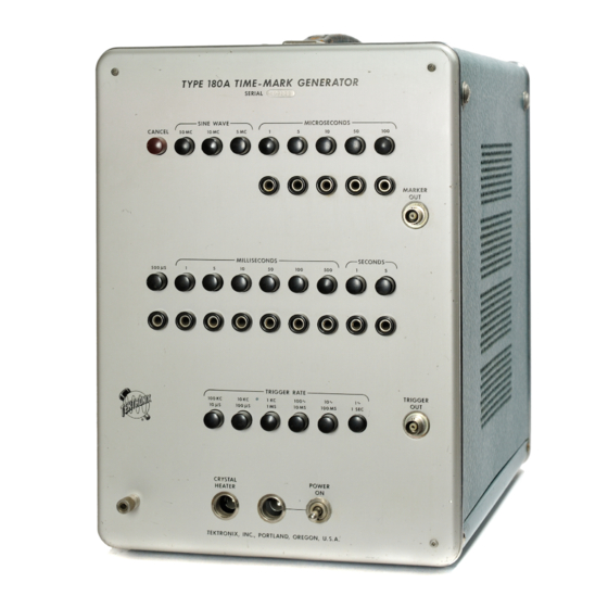
CONTENTS Warranty Section 1 Characteristics Section 2 Operating Instructions Section 3 Circuit Description Section 4 Maintenance Second 5 Calibration Procedure Parts List and Schematics Section 6... - Page 4 IlS iS f t : : ' # TYPE 180A T IM E - M A R K G E N E R A T O R ■ ' ■ '' .""" "' ■ ' ■ ft i: © © © © ©...
- Page 5 TRIGGER Millisecond markers at intervals of 1, 5, 10, 50, 100 and connector on the front panel of the Type 180A. The trigger 500 milliseconds. pulses are also selected by the operation of a push-button One-second and five-second interval markers. Sine-waves switch.
- Page 6 Characteristics — Type 1 80A Finish— photoetched, anodized panel. Blue vinyl, perfor Other Characteristics ated cabinet. Crystal O scillator Dimensions— 13'/2" high, 93 /4" wide, 17” depth. Weight— 31 pounds. Frequency— 1 me ± 1 0 c p s. May be accurately set for 1 me.
-
Page 7: Operating Instructions
Be sure the bottom panel is installed according to directions. The Type 180A may be operated in any normal indoor location, or in the open if protected from moisture. If the instrument has been exposed to dampness, it should be... - Page 8 T702. The lower drawing indicates the position of the terminal strips. Fan Connections Coaxial Cables are furnished with the Type 180A. If you desire to get the optimum risetime from your instrument The fan is connected across a portion of the primary of...
- Page 9 In the 1-jU.sec Amp and CF stage, the sigpal is amplified for coupling to the front-panel l-/xsec banana jack and In the Type 180A, time-marker and sine-wave outputs are push-button switch. The output from this stage is also con derived from a one-megacycle oscillator. The time-marker nected to the input of the 5-mc Multiplier.
-
Page 10: Circuit Description
The output waveform at the plate of V100B is capaci- Basic Multivibrator tively coupled to the grid of the l-/j.sec Amplifier, V104B, There are 13 frequency dividers in the Type 180A, pro direct coupled to the Isolating Cathode Follower, ducing thirteen of the fourteen output time markers. (The V100A. - Page 11 Circuit Description — Type 1 80A Fig. 3-2 Basic 5-fisec. multivibrator. Circuit numbers have been changed for simplification. follower V100A. The function of the cathode follower is to mitting the tube to conduct. As the tube conducts, the pulse is coupled to the grid of V2 through capacitor C l. The isolate the loading effects of the multivibrator triggering negative pulse breaks the clamping action of V4, driving circuit from the oscillator.
- Page 12 5-p.sec triggering pulse. A thermal cut-out is provided in the primary of T701 to open the circuit should the Type 180A internal temperature rise too high. The device is set to open at 137-degrees EXTERNAL TRIGGERING Fahrenheit.
- Page 13 Circuit Description — Type 1 80A A small sample of the unregulated-bus ripple will appear V433B. C770, connected between -17-vo lt supply at the screen of V724 through R724. This ripple signal and ground aids in filtering the output of the supply. appearing at the screen (which acts as an injector grid) —...
- Page 14 NOTES...
-
Page 15: Maintenance
Care must be taken to assure free ventilation of the Type resistors, missing tube shields, or broken terminal strips. 180A inasmuch as some of the components are operated at For most visual troubles the remedy is apparent; however dissipation levels such that excessive interior temperatures particular care must be taken when heat-damaged com... - Page 16 If you prefer, you can order the solder directly from Tektronix in one pound rolls. Order by Tektronix part number 251-514. Because of the shape of the terminals on the ceramic...
- Page 17 Snip off the portion of the mounting post which protrudes Each part in your instrument has a 6-digit Tektronix part below the nylon collar on the reverse side of the chassis. number. This number, together with a description of the part, will be found in the parts list.
- Page 18 The procedure given in Step 3 of the Calibration circuit the power supply should be checked. Proper opera tion of every circuit within the Type 180A is dependent Procedure can be used to check the operation of the divider upon the proper operation of the regulated power supply.
- Page 19 Maintenance — Type 1 80A voltage at the left-hand plate should be equal to the supply If these measures fail to locate the trouble in the circuit, voltage (+ 225 volts). The voltage at the right-hand plate a check of the various circuit components is indicated. should be down by a considerable amount, possibly as low as +100 volts.
- Page 20 NOTES...
-
Page 21: Calibration Procedure
105 to 125 volts. The power supply regulating circuits of the Type 180A are capable of holding the ripple present on the output 6. A 50-ohm Terminating Resistor and a Type P93 93-ohm voltage to a very low level. - Page 22 3. Dividing Rate Adjustment the test oscilloscope input between ground and the — 150- volt bus at the point indicated in Fig. 5-1. The Tektronix The dividing stages in the Type 180A are cathode- Type A-100 Clip-Lead Adapter (part number 013-003) or a...
- Page 23 INTERNAL Table 5-1 indicates the necessary front-panel control SWEEP settings for the test oscilloscope and the Type 180A. It POWER also indicates the appropriate screwdriver adjustment for Type L: each setting of the front-panel push button on the Type 180A. To adjust the Type 180A divider circuits, set the...
- Page 24 HORIZONTAL POSITION centered Switch the 5X M AGNIFIER to O N and display a fifty- POWER megacycle sine wave from the Type 180A. Adjust 0 4 3 and 0 47 for a fifty-megacycle display (one cycle per centimeter) SQUARE-W AVE CALIBRATOR of maximum amplitude.
- Page 25 In addition to being marked with the appropriate frequency, each trigger push button is marked Accuracy of the time markers in the Type 180A depends with its value in time. For example, the 100 KC trigger upon the precise adjustment of the frequency of the 1 MC button is also marked 1 0 //.S.
- Page 26 Calibration Procedure — Type 1 80A 1 0 /is 5 0 /is M A R K E R O U T 100 /i s 5 0 0 /is 1 MS T R IG G E R O U T 5 M S Fig .
- Page 27 MARKER This adjustment of C l 05 will not effect the other markers O U T terminal of the Type 180A and insert a short (12 or as they are timed by this basic frequency and will follow 15 inch) piece of wire in the center of the terminator.
- Page 28 NOTES...
-
Page 29: Parts List And Schematics
X000 Part first added at this serial number. 000X Part removed after this serial number. *000-000 Asterisk preceding Tektronix Part Number indicates manufactured by or for Tektronix, also reworked or checked components. Use 000-000 Part number indicated is direct replacement. - Page 30 Parts List and Schematics— Type 1 80A HOW TO ORDER PARTS Replacement parts are available from or through your local Tektronix Field Office. Changes to Tektronix instruments are sometimes made to accommo date improved components as they become available, and to give you the benefit of the latest circuit improvements developed in our engineer...
- Page 31 Parts List — Type 180A ELECTRICAL PARTS LIST Values are fixed unless named variable. Tektronix Ckt. No. Part No. Description Bulbs B101 150-001 Incandescent # 4 7 Crystal Oven B701 150-001 Incandescent # 4 7 Pilot Light 158-007 Crystal Oven Assembly Capacitors Tolerance ±...
- Page 32 Parts List — Type 180A Capacitors (continued) Tektronix Ckt. No. Part No. Description S/N Range C l 63 283-000 .001 /if Disc. Type 500 v C l 67 281-542 18 pf Cer. 500 v C177 281-509 15 pf Cer. 500 v...
- Page 33 Parts List — Type 180A Capacitors (continued) Tektronix Ckt. No. Part No. Description S/N Range C422 281-518 47 pf Cer. 500 v C427 285-553 1 /if 600 v C437 281-536 1000 pf Cer. 5001-5478 500 v 283-001 .005 ^ Disc. Type...
- Page 34 Parts List — Type 180A Inductors (continued) Tektronix Ckt. No. Part No. Description S/N Range LR171 *108-068 600 fx h (on 3.3 k, 1 w , resistor) 5001-5478 *108-155 1 mh (on 10 k, 1 w , resistor) 5479-up LI 77 *108-065 1.1 mh...
- Page 35 Parts List — Type 180A Resistors (Cont'd.) Tektronix Ckt. No. Part No. Description S/N Range lo o RT 54 302-101 R155 304-333 33 k 5001-5478 306-273 27 k 5479-up R161 305-682 6.8 k R163 302-102 lo o n R164 302-101...
- Page 36 Parts List — Type 180A Resistors (continued) Tektronix Ckt. No. Part No. Description S/N Range R241 301-103 R242 301-183 1 0 0 o R244 302-101 R245 305-393 39 k 5001-5478 305-273 27 k 5479-up R247 309-026 3 meg Prec. 5001 -5478...
- Page 37 Parts List — Type 180A Resistors (continued) Tektronix Ckt. No. Part No. Description S/N Range R304 302-101 100 o R305 305-473 47 k R307 Use 309-093 4 meg Prec. R308 311-044 5 meg Var. 5 mSEC R310 302-101 1 0 0...
- Page 38 Parts List — Type 180A Resistors (continued) Tektronix Ckt. No. Part No. Description S/N Range R377 302-154 150 k v% w R378 302-221 220 0 Y2 w 5001 -5478 302-272 2.7 k y 2 w 5479-up R381 301-333 33 k...
- Page 39 Parts List — Type 180A Resistors (continued) Tektronix Ckt. No. Part No. Description S/N Range R507 302-182 1.8 k y2 w R509 302-182 1.8 k R511 302-182 1.8 k R513 302-182 1.8 k R515 302-182 1.8 k R517 302-182 1.8 k...
- Page 40 Parts List — Type 180A Resistors (continued) Tektronix Ckt. No. Part No. Description S/N Range R744 309-090 50 k Prec. R746 302-105 1 meg R750 302-183 R754 302-155 1.5 meg R758 302-102 R762 302-333 33 k R770 5001-5479X 301-393 39 k...
- Page 41 Parts List — Type 180A Electron Tubes (continued) Tektronix Ckt. No. Part No. Description S/N Range V245 154-147 5965 V253 154-041 12AU7 V262 154-016 6AL5 V265 154-147 5965 V273 154-041 12AU7 V282 154-016 6AL5 V285 154-147 5965 V293 154-041 12AU7...
- Page 42 Parts List — Type 180A Mechanical Parts List Tektronix Part Number Adapter, 3 wire to 2 wire S/N 5552-up 103-013 Angle, frame bottom S/N 5001-6617 122-044 Angle, frome bottom, blue vinyl S/N 6618-up 122-062 Bar, 3 U x y2 x 1 w/2-32 holes 381-084 Bar, .125 x 1 9 /32 x 37 /8 switch cancelling...
- Page 43 Parts List — Type 180A Mechanical Parts List (continued) Tektronix Part Number Chassis, divider A 441-175 Chassis, power S/N 5001-6385 441-178 Chassis, power S/N 6386-up 441-307 Clamp, cable 5 /16" plastic 343-004 Clamp, cable % " plastic 343-007 Connector, chassis mount 2 cont. male...
- Page 44 Ports List — Type 180A Mechanical Parts List (continued) Part Number Tektronix Nut, hex 10-32 x 5 /u 210-410 Nut, hex 3 /8- 3 2 x y 2 210-413 Nut, hex 1 5 /32-32 x % 6 210-414 Nut, hex y 2 x 5 /e with 3 /8-32 int. thread...
- Page 45 Parts List — Type 1 80A Mechanical Parts List (continued] Tektronix Part Number Screw, 6-32 x 5 /]6 BHS 211-507 Screw, 6-32 x 3 /3 FHS 211-509 Screw, 6-32 x 3 /e BHS 211-510 Screw, 6-32 x % FHS, 100°...
- Page 46 Parts List — Type 180A Mechanical Parts List (continued) Tektronix Part Number Strip, ceramic % x 7 notches, clip mounted 124-089 Strip, ceramic % x 9 notches, clip mounted 124-090 Strip, ceramic 3 /4 x 11 notches, clip mounted 124-091...
- Page 47 MANUAL CHANGE INFORMATION A t Tektro nix, we co ntin ually strive to keep up with latest electronic developm ents by adding circuit and component improvements to our instruments as soon as they are developed and tested. Sometimes, due to printing shipping req uire...
- Page 49 T Y P E 180A MOD 5307 Direct Replacement (30) V 124 Change to 6DK6/8.136 154-367 V I 34 Change to 6DK6/8136 154-367 V 144 Change to 6DK6/8136 154-367...
- Page 51 T Y P E 132 - Tent. S/N 1000 T Y P E 133 - Tent.S/N 450 T Y P E 180A - Tent. S/N 9410 CONNECTOR, CHASSIS MOUNTED ” D" HOLE UHF 131-081 CHANGE TO: CONNECTOR, CHASSIS MOUNTED, "D" HOLE, BNC...
Need help?
Do you have a question about the 180A and is the answer not in the manual?
Questions and answers