
Subscribe to Our Youtube Channel
Related Manuals for Gree GRS-Cm28/NaA-M


Summary of Contents for Gree GRS-Cm28/NaA-M
- Page 1 CIRCULATING AIR SOURCE HEAT PUMP WATER HEATER SERVICE MANUAL T1/R410A/50Hz (GC201510 – ІІ)
-
Page 2: Table Of Contents
Contents CHAPTER Ⅰ PRODUCT INTRODUCTION ............1 1. I .......................... 1 NTRODUCTION OF 2. B ........................2 ASIC ORKING RINCIPAL 3. B ........................4 ASIC ARAMETERS OF 4. O ..........................5 PTIONAL ITTINGS CHAPTER Ⅱ INSTALLATION .................. 6 1. I ........................ -
Page 3: Chapter Ⅰ Product Introduction
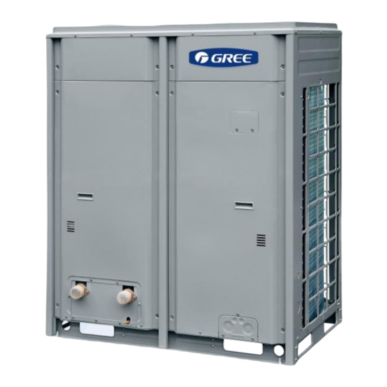
) Ⅰ Product Introduction Chapter Unit Chapter Ⅰ Product Introduction 1. Introduction of Unit 1.1 Product Overview GRS-Cm28/NaA-M GRS-Cm28/NaA1-M GRS-Cm53/NaA-M、GRS-Cm53/NaA1-M GRS-Cm36/NaA-M GRS-Cm36/NaA1-M 1.2 Operating Range of Unit Product operation range Item Outdoor ambient temperature Operation range for generating hot water... -
Page 4: Basic Working Principal
(2. Basic Working ) Ⅰ Product Introduction Chapter Principal 2. Basic Working Principal 2.1 Introduction of Working Principal Electric energy input Evaporator Condenser Exit pipe of hot water Compressor Backwater pipe Water Gas-liquid separator Bushing condenser tank Air source energy input Water supply pipe Inlet pipe of cold water Strainer... - Page 5 (2. Basic Working ) Ⅰ Product Introduction Chapter Principal 2.2 Name and Main Function of Different Parts Name Main Function Acting as the heat of water heater system, compress the Compressor refrigerant to be high-temperature and high-pressure gas, promote the flowing of refrigerant inside the system. Oil temperature heating belt of Under stand-by status, keep the oil temperature of compressor;...
-
Page 6: Basic Parameters Of Unit
(3. Basic Parameters ) Ⅰ Product Introduction Chapter of Unit 3. Basic Parameters of Unit GRS-Cm28/NaA-M GRS-Cm36/NaA-M GRS-Cm53/NaA-M Model GRS-Cm28/NaA1-M GRS-Cm36/NaA1-M GRS-Cm53/NaA1-M ER01000150 ER01000160 ER01000170 Product Code ER01000180 ER01000190 ER01000200 Heating capacity Heating Power Input Hot water mode Heating Current Input 13.9... -
Page 7: Optional Fittings
(4. Optional Fittings) Ⅰ Product Introduction Chapter ⑤Circulating water flow means the rated flow during the heating operation. When selecting the water pump model, it shall refer to the flow after overcoming the water resistance, that is, the flow of corresponding delivery lift, rather than the maximum flow labeled in the nameplate of water pump. -
Page 8: Chapter Ⅱ Installation
(1.Installation Flow Chart) Ⅱ Installation Chapter Chapter Ⅱ Installation 1.Installation Flow Chart Submit the design draft Selection of material Examine and verify the on-site installation position Install water tank Install outdoor unit Install water-side pipelines and valves Connect power cord and communication wire Heat insulation connect water tank and outdoor unit Debugging of uni... - Page 9 (2. Preparation Before ) Ⅱ Installation Chapter Installation Warning! During the installation and construction, personal and property safety must be placed in the first place. During the construction, constructors must abide by the national related safety criterion to avoid personal injury or property loss. 2.1.2 Importance of installation Water heater adopts direct evaporative type cooling system, which has high requirement for the cleanliness and dryness of inner pipelines of the system.
- Page 10 (2. Preparation Before ) Ⅱ Installation Chapter Installation unit; 3)If there are no reserving holes, the holes can be drilled, but it is not allowed to drill on the spandrel girder or load bearing wall. 4)Pipelines for cooling water, hot water and return pipe should be prearranged, and should reserve interfaces for the pipelines of cooling water, hot water and return pipe;...
- Page 11 (2. Preparation Before ) Ⅱ Installation Chapter Installation installation personnel should seek confirmation from the designer and make a Design Alteration Record in written form. 2.3 Selection of Installation Materials 2.3.1 Notices for Selecting Installation Materials 1)If the brand and dimension of installation materials are designated, users should purchase the materials according to the requirements;...
-
Page 12: Installation For Main Unit Of Water Heater
Chapter Six. 3. Installation for Main Unit of Water Heater 3.1 External Dimensions and Size of Installation Holes (1) External dimensions and size of installation holes for GRS-Cm28/NaA-M 、 GRS-Cm28/NaA1-M、GRS-Cm36/NaA-M、GRS-Cm36/NaA1-M: Unit: mm (2) External dimensions and size of installation holes for GRS-Cm53/NaA-M 、... - Page 13 5)The unit should be installed in the place where is convenient for installing connecting pipe and electricity. 3.3 Installation Space Requirement (1) Installation space for GRS-Cm28/NaA-M、 GRS-Cm28/NaA1-M、 GRS-Cm36/NaA-M、 GRS-Cm36/NaA1-M 、GRS-Cm53/NaA-M、GRS-Cm53/NaA1-M units (Unit: mm): Single Installation...
- Page 14 (3. Installation for ) Ⅱ Installation Chapter Main Unit of Water Heater cmultiple installation 3.4 Manufacture of Installation Base The concrete base in the installing place of outdoor unit should have enough strength, and the drainage should be in good condition that should not influence the drainage of floor or the drainage of the downstairs.
-
Page 15: Design Of Water System
(4. Design of ) Ⅱ Installation Chapter Water System Methods for making a concrete base are as following: 1)The concrete base should have enough rigidity and intensity to bear the operating weight with a flat surface and 200~300mm height; the base should have a proper size according to the size of unit for later maintenance;... - Page 16 (4. Design of ) Ⅱ Installation Chapter Water System 8~10 working hours per day, so as to ensure that the water heater can satisfy the hot water demand of building under the worst working condition. 3)Determine the model and quantity of unit according to the area of installing place, bearing weight and other factors.
- Page 17 (4. Design of ) Ⅱ Installation Chapter Water System Name Instruction of Function Remarks During the debugging and maintenance of unit, the cut-off valve can be Cut-off valve manually opened and closed to control the water. It is suggested to use PPR tubes and Pipelines For supplying domestic water pipes...
- Page 18 (8) When selecting unit model of circulating water pump, please ensure that the circulating water flow volume of unit should not be less than the following stipulated value: Sheet 3 Circulating Heat Insulation Flow Volume Requirements Unit Model Circulating Heat Insulation Flow Volume(m /h) GRS-Cm28/NaA-M ≥4.8 GRS-Cm28/NaA1-M GRS-Cm36/NaA-M ≥6.2 GRS-Cm36/NaA1-M GRS-Cm53/NaA-M ≥9.2...
- Page 19 (4. Design of ) Ⅱ Installation Chapter Water System Installation Sketch Mpa of Modularized System Notes: ① When the unit is installed lower than the water tank, then the height difference between the water tank and the unit should not be larger than 8m, otherwise there should install an intermediate transitive water tank;...
- Page 20 (4. Design of ) Ⅱ Installation Chapter Water System ⑥ When user is using water, the user water supply water pump will be controlled by the by electric contact manometer or water flow switch (equipped by project). Meanwhile, they will send the power-off command to backwater solenoid valve.
-
Page 21: Installation And Heat Insulation For Pipelines Of Water System
(5. Installation and ) Ⅱ Installation Chapter Heat Insulation for Pipelines of Water System and the matching among water level switches. Please pay attention to the following points during installation: (1)The water-getting outlet of user should be 50mm (minimum) higher than the circulating water outlet to prevent water-lacking during operation. - Page 22 (5. Installation and ) Ⅱ Installation Chapter Heat Insulation for Pipelines of Water System requirements: The pipe materials and parts should be light-tight with smooth inner and outer walls, the wall thickness should be even without air bubble, scratch marks and other defects. Interface of pipe material should be level, and the end face should be vertical to the axes of pipe.
- Page 23 (5. Installation and ) Ⅱ Installation Chapter Heat Insulation for Pipelines of Water System Design Pressure (MPa) Type Material PD≤0.6 0.6<PD≤0.8 0.8<PD≤1.0 Cold water pipe PP-R Hot water pipe PP-R S3.2 S2.5 5.1.2 Installation for pipelines of water system When the PP-R pipe is connected by hot welding, the welding machines and tools should be specially provided or acknowledged by pipe material manufacturers.
- Page 24 (5. Installation and ) Ⅱ Installation Chapter Heat Insulation for Pipelines of Water System the position with auxiliary mark in the rectilinear direction of pipes according to the requirements of design drawing; 7) When connecting pipes, insert the pipe end into heating jacket to the marked depth without rotating the pipe end, and at the same time push the pipe parts to heating head where has marked;...
- Page 25 (5. Installation and ) Ⅱ Installation Chapter Heat Insulation for Pipelines of Water System 17)When installing the pipes, there should not be axial distortion. When the pipe is penetrated to the walls or the floors, do not compulsorily adjust it. When the PP-R pipe is installed in parallel with other metal pipelines, they should keep a certain protection distance that the net distance should not be less than 100mm.
- Page 26 (5. Installation and ) Ⅱ Installation Chapter Heat Insulation for Pipelines of Water System Maximum Distance for Support/Hanger Frame of Cold Water Pipe (mm) Nominal outer diameter dn Transverse 1000 1100 1200 1350 1550 pipe Vertical pipe 1000 1100 1300 1600 1800 2000...
- Page 27 (5. Installation and ) Ⅱ Installation Chapter Heat Insulation for Pipelines of Water System circulating flow reaches its closed flow, it is used to output closed loop circuit; when water flow is smaller than a certain flow, water flow switch will send out a break-off signal to stop the units and thus protect compressor, water pump and other important components.
- Page 28 5.3 Installation of Water Level Switch 5.3.1 Installation of Electrode Type Water Level Switch Gree commercial water heater adopts 4-level water level switch and one-level water level switch. 4-level water level switch is applied in heating water tank and one-level water level switch is applied in heat-accumulating water tank.
- Page 29 (5. Installation and ) Ⅱ Installation Chapter Heat Insulation for Pipelines of Water System Sheet 1 Icon Name Icon Name Operation indicator On/Off button Power indicator Exit/Return button Error indicator Confirm button Up button Functional button 4 Right button Functional button 3 Menu button Functional button 2 Down button...
- Page 30 (5. Installation and ) Ⅱ Installation Chapter Heat Insulation for Pipelines of Water System After entering user parameters setting menu, hold on pressing Right button to enter water level setting mode; hold on pressing ▲ button or ▼ button to adjust parameter value continuously. There are six kinds of water level mode for option.
- Page 31 (5. Installation and ) Ⅱ Installation Chapter Heat Insulation for Pipelines of Water System Notices: The detecting signal wire must be connected to the corresponding water level according to the color. Otherwise, it may lead to damage of unit or water overflow; ...
- Page 32 (5. Installation and ) Ⅱ Installation Chapter Heat Insulation for Pipelines of Water System (5)Installation Dimension of Wiring Box (6)Error and Solution ○ 1 Please confirm if the detecting signal wire, communication wire or water level switch wire is connected; ○...
- Page 33 (5. Installation and ) Ⅱ Installation Chapter Heat Insulation for Pipelines of Water System service staff. (7)Installation Example Rated accessories Detecting electrode (totally 4 piece in the Wired controller Detection board Wiring box color of red, brown, black and yellow) ①...
- Page 34 (5. Installation and ) Ⅱ Installation Chapter Heat Insulation for Pipelines of Water System ③ Finally, put the non-metal rod vertically into the water tank and fix it. From bottom to top, the sequence is #1 detecting electrode, #2 detecting electrode, #3 detecting electrode, #4 detecting electrode.
- Page 35 (5. Installation and ) Ⅱ Installation Chapter Heat Insulation for Pipelines of Water System (2)Installation Notes: ① When installing water level switch, please follow installation sketch map strictly. One-level water level switch is equipped with G1/8” external thread and nut, and also one L-type sheet metal piece (can be fixed on the water tank).
-
Page 36: Electric Installation
(6. Electric Installation) Ⅱ Installation Chapter measures. 4) The heat insulating measures can conduct by referring to heat insulating measures of steel pipes Nominal outer 20~32 40~50 63~90 diameter dn Heat insulating Obturator foramen foaming rubber and plastic heat insulating pipe material Thickness for heat insulating mm... - Page 37 Configuration Table of Power Source Capacity of Air Minimum Sectional Area of Power Cord (mm Type of Power Switch Model Source (A) Phase Line Zero Line Earth Wire GRS-Cm28/NaA-M 380V-415V 3N~ GRS-Cm28/NaA1-M 50Hz GRS-Cm36/NaA-M 380V-415V 3N~ GRS-Cm36/NaA1-M 50Hz GRS-Cm53/NaA-M 380V-415V 3N~ GRS-Cm53/NaA1-M...
- Page 38 (6. Electric Installation) Ⅱ Installation Chapter according to the national standard. ③The specification of circuit breaker in the above table is based on the conditions that the ambient temperature is 40℃, the air switch is “D”. If it is not under the aforesaid conditions, please adjust according to the specification manual of circuit breaker.
- Page 39 (6. Electric Installation) Ⅱ Installation Chapter 6.2.3 External wiring diagram of unit 6.2.4 External wiring diagram of modularized unit inspection board Wired controller CN25 CN25 CN25 CN15 CN15 CN15 1#unit 2#unit 3#unit...
- Page 40 (6. Electric Installation) Ⅱ Installation Chapter 6.3 Circuit Diagram 1)Diagram of GRS-Cm28/NaA-M: 2) Circuit diagram of GRS-Cm28/NaA1-M:...
- Page 41 (6. Electric Installation) Ⅱ Installation Chapter 3) Circuit diagram of GRS-Cm36/NaA-M: 4) Circuit diagram of GRS-Cm36/NaA1-M:...
- Page 42 (6. Electric Installation) Ⅱ Installation Chapter 5) Circuit diagram of GRS-Cm53/NaA-M: 6) Circuit diagram of GRS-Cm53/NaA1-M: Notes: The above diagrams are only for reference, specific information should be subject to the circuit diagram stuck on the actual unit.
-
Page 43: Installation Of Communication System
(7. Installation of ) Ⅱ Installation Chapter Communication System 7. Installation of Communication System This unit adopts RS485 communication method. The wired controller can control single unit, and can control multiple units as well. The wired controller has BMS interface that can connect to computer through RS232 transferring to RS485 convertor, so as to realize remote control. - Page 44 Sketch map for connection of wired controller communication wire. When it needs to connect to PC, it can connect from the BMS interface. 7.2 Connecting Method for Communication Network (It is applicable to GRS-Cm28/NaA-M,GRS-Cm28/NaA1-M,GRS-Cm36/NaA-M, GRS-Cm36/NaA1-M,GRS-Cm53/NaA-M,GRS-Cm53/NaA1-M) 7.2.1 Connecting method for single module...
-
Page 45: Charging Of Refrigerant
(8. Charging of ) Ⅱ Installation Chapter Refrigerant 7.2.2 Connecting method for multiple module 8. Charging of Refrigerant 8.1 Leak Detection of System Generally we use soapy water to conduct lead detection. Smear soapy water to the points where are possible to leak (welding points, spools, joints, etc.), if there are bubbles, it means there is leakage, it should be welded again or repaired. - Page 46 (8. Charging of ) Ⅱ Installation Chapter Refrigerant 8.3 Recharging of Refrigerant 1)Connect the intermediate soft tube of refrigerant meter to the refrigerant tank, and connect one end of blue soft tube of low pressure gauge to Freon charging spout of air intake duct and clip it on, open the valve of refrigerant tank, and then open the valve beside the low pressure gauge of refrigerant meter to discharge for 5 seconds, screw down the joint of soft tube of refrigerant meter on the three-way valve.
- Page 47 (8. Charging of ) Ⅱ Installation Chapter Refrigerant 9. Examination After Installation After finishing the installation, please conduct check and examination according to the following sheet. Contents for Items for Examination Results Installation 1)Check if the installing place of outdoor unit has Pass□...
-
Page 48: Chapter Ⅲ Debugging And Operation
(1. Debugging Flow ) Ⅲ Debugging and Operation Chapter Chart Chapter Ⅲ Debugging and Operation 1. Debugging Flow Chart Check before debugging Outdoor unit Electrical Water tank Turn on unit for Parameters of outdoor unit Parameters of water tank Finish debugging 2. -
Page 49: Pre-Debugging Preparations
(3. Pre-debugging Preparations) Ⅲ Debugging and Operation Chapter product and national and local security operation requirements. Rule-breaking operations are prohibited; It is forbidden to directly connect the compressor with power supply and forcibly power it on. 3. Pre-debugging Preparations 3.1 Required Tools for Debugging (1)Shifting spanner (2)Inner hexagon spanner (3)Straight screwdriver... - Page 50 (3. Pre-debugging Preparations) Ⅲ Debugging and Operation Chapter Spot Check for air source water heater Spot Check Item Qualified Does the unit installation heat exchange space comply with requirements? There should be discharge ditch or discharge outlet nearby the installation position of the unit for convenient drainage.
- Page 51 (3. Pre-debugging Preparations) Ⅲ Debugging and Operation Chapter 2)Check if the insulation measure of water tank is sufficient. If the insulation measure of water inlet pipe, water outlet pipe and water supplementary pipe is sufficient. 3)Check if the water tank water level switch, temperature sensor, controller, pressure meter, pressure relief valve, auto discharge valve, etc.
-
Page 52: Debugging Operation
(4. Debugging Operation) Ⅲ Debugging and Operation Chapter 3.3.5 Selection of wired controller installation location 1) The wired controller cannot be installed in high temperature and high humidity places, such as kitchen and bathroom. 2)It is suggested to install the wired controller indoors. If it is installed outdoors, an opaque rainproof protection box shall be applied in order to prevent the wired controller from direct sunshine or rain. - Page 53 Chapter Ⅲ Debugging (4. Debugging ) and Operation Operation (1) If the switch of wired controller works normally. (2) If each function button works normally. (3) If the indicator of main board is on. (4) Press the electric heating operation button and see if the button works normally. (5) If the drainage is smooth.
- Page 54 Chapter Ⅲ Debugging (4. Debugging ) and Operation Operation 4.4 Finish Debugging Operation Record the unit operation parameters Debugging operation parameters Engineering project name Unit model Debugging personnel Debugging date Rated capacity of outdoor Capacity of water tank unit(kW) Max difference between Lift of pump ODU and water tank(m) Debugging status: □...
-
Page 55: Unit Function Settings
Chapter Ⅲ Debugging (5. Unit ) and Operation Function Settings parameters of unit can refer to the parameters of nominal working condition. Engineering Unit model project name Debugging Date personnel Capacity of water tank(m Flow: Choose the model according Rated flow(m3/h) and lift(m) of circulating pump Lift: to the lowest temperature Circulating water... - Page 56 Chapter Ⅲ Debugging (5. Unit ) and Operation Function Settings If the system is constituted by one set of unit, the professional debugging person only have to check and confirm whether the DIP is 1# because the address DIP is set at 1# unit at ex-factory.
- Page 57 Chapter Ⅲ Debugging (5. Unit ) and Operation Function Settings Address DIP diagram:...
-
Page 58: Chapter Ⅳ Maintenance
Chapter Ⅳ Maintenance(1. Error ) Code Chapter Ⅳ Maintenance 1. Error Code Error Source of Error name Control logic code error signal The high pressure switch is used to detect the high pressure of system and protect the unit from operating in an abnormal status. When the high pressure of the system exceeds the set value, the corresponding High pressure High pressure... - Page 59 Chapter Ⅳ Maintenance(1. Error ) Code Water flow switch protection aims to prevent over-high fluorine system pressure of the unit arising from over-low entering water pressure or poor water flow. When disconnection of the water flow switch is detected Water flow Water flow during operation, unit will stop and the water makeup valve will be closed.
- Page 60 Chapter Ⅳ Maintenance(1. Error ) Code When the high-level water level switch indicates that water level is high Water level and the low-level water level switch indicates that water level is low, the Water level switch error of unit reports the water level switch error. If the error setting is absent, unit switch the water tank will start or stop abnormally.
-
Page 61: Troubleshooting
Chapter Ⅳ Maintenance(2. Troubleshooting) 2. Troubleshooting 2.1 System Troubleshooting 2.1.1 High pressure protection High pressure protection Wire connection error or Adjust the line and line interference. Check and eliminate the replace the line interference Check if the pressure switch is Replace the pressure switch damaged Short circuit of the main board... - Page 62 Chapter Ⅳ Maintenance(2. Troubleshooting) 2.1.2 Low pressure protection Low pressure protection Use a pressure gauge to Check if short circuit occurs to Wire connection error or line Check if the pressure switch is measure whether the pressure is low the main board protection interface interference;...
- Page 63 Chapter Ⅳ Maintenance(2. Troubleshooting) 2.1.3 High discharge temperature protection High discharge temperature protection Replace the discharge temperature High discharge temperature protection Measure if the sensor resistance is correct sensor The main board fails. Replace the main board Check if the electronic expansion valve Replace the expansion valve coil or the valve can operate normally Check if the temperature decrease or...
- Page 64 Chapter Ⅳ Maintenance(2. Troubleshooting) Water flow switch protection The switch Disconnect power. Turn power signal cable falls on after cable is reconnected The butt piece Adjust the butt piece is clamped between angle and size pipe walls The butt piece is Replace the butt piece broken Replace the water...
- Page 65 Chapter Ⅳ Maintenance(2. Troubleshooting) 2.1.7 Temperature sensor error Temperature sensor error Check if the temperature sensor Confirm the positions of the plug plug and the socket on the main board and socket are connected correctly Remove the sensor. Measure if its Replace the sensor resistance is in the normal range Replace the main board...
- Page 66 Chapter Ⅳ Maintenance(2. Troubleshooting) the main board. If yes, go check the err code. ②Powered on the machine. Use a voltage meter to test the power supply check point as the figure below shows, the voltage should be 187V~264V,If there is no power, check whether the power supply connection of the main board is correct.
- Page 67 Chapter Ⅳ Maintenance(2. Troubleshooting) 2.3 Other Common Errors and Their Causes Error phenomenon Causes Troubleshooting A、There‟s problem for the power ●Check the phase sequence. Compressor can‟t ●Check it and connect it tightly. B、Wire connection is loose ●Check the malfunction cause and resolve it. be started up C、Malfunction of relay or fuse ●Replace compressor.
-
Page 68: Maintenance Of Key Parts
Chapter Ⅳ Maintenance(3. Maintenance ) of Key Parts 3. Maintenance of Key Parts 3.1 Introduction of Key Parts Picture Name Function It uses electricity as the driving power to compress refrigerant into high temperature and high pressure gas and makes it Compressor overcome resistance in the cooling system to flow circularly and constantly. - Page 69 3.2 Removal/Installation of Key Parts 3.2.1 Removal/Installation of GRS-Cm28/NaA-M、GRS-Cm28/NaA1-M main unit 3.2.1.1 Compressor Removal/ Installation of the compressor Remarks: Before removing the compressor, make sure there is no refrigerant in unit‟s pipeline system and power supply is cut off.
- Page 70 Chapter Ⅳ Maintenance(3. Maintenance ) of Key Parts Compressor 2 、 Remove ● Use bending bar or other the nuts fixing the tools to unfasten the compressor compressor fixing nuts. footing. ● When using a soldering gun, weld the pipes quickly to prevent pipeline from 3、Cut off the overburning;...
- Page 71 Chapter Ⅳ Maintenance(3. Maintenance ) of Key Parts ● Detect system leakage; ● Make sure the vacuum 6 、 Retain system pressure, degree reaches -1.0bar; —— ● Type amount vacuumize recharge refrigerant should accord with requirements unit‟s refrigerant. nameplate. 3.2.1.2 Gas-liquid separator Removal/ Installation of the gas-liquid separator and liquid storage tank.
- Page 72 Chapter Ⅳ Maintenance(3. Maintenance ) of Key Parts 、 Assemble and weld ● Use soldering gun to connection weld the pipes; pipe ● Note: Add nitrogen gas-liquid when welding. separator. Add nitrogen during welding protection. ● Detect system leakage; ● Make sure the 4 、...
- Page 73 Chapter Ⅳ Maintenance(3. Maintenance ) of Key Parts 2、Take off ● Take off the fixing nuts the fixing nuts of by using a spanner or tube tube other tools; condenser and ● Remove the tube in then remove the tube condenser from the tube tube base plate.
- Page 74 Chapter Ⅳ Maintenance(3. Maintenance ) of Key Parts ● Disconnect power of the unit; 1 、 Reclaim ● Reclaim the refrigerant. refrigerant. ● In order to protect the EXV, wrap it with wet 2、Remove cloth during welding; electronic ● Remove the EXV by expansion valve using the soldering gun.
- Page 75 Chapter Ⅳ Maintenance(3. Maintenance ) of Key Parts 3.2.1.5 4-way valve Removal/ Installation of 4-way valve Remarks: Before replacing, cut off the power and reclaim refrigerant. Step Figure Operation Instructions ● Reclaim the refrigerant; ● Before removing the 1 、 Reclaim 4-way valve, please refrigerant.
- Page 76 Chapter Ⅳ Maintenance(3. Maintenance ) of Key Parts Removal/ Installation of electronic expansion valve Remarks: Check the refrigerant system and each circuit. After making sure that it is necessary to replace electronic expansion valve, disconnect power and reclaim the refrigerant. Step Figure Operation Instructions...
- Page 77 Chapter Ⅳ Maintenance(3. Maintenance ) of Key Parts 3.2.1.6 Strainer Removal/ Installation of strainer Remarks: Check the refrigerant system and each circuit. After making sure that it is necessary to replace the filter, disconnect power and reclaim the refrigerant. Step Figure Operation Instructions ●...
- Page 78 Chapter Ⅳ Maintenance(3. Maintenance ) of Key Parts 3.2.2 Removal/Installation of GRS-Cm36/NaA-M、GRS-Cm36/NaA1-M main unit 3.2.2.1 Compressor Removal/ Installation of the compressor Remarks: Before removing the compressor, make sure there is no refrigerant in unit‟s pipeline system and power supply is cut off. Step Figure Operation Instructions...
- Page 79 Chapter Ⅳ Maintenance(3. Maintenance ) of Key Parts ● Place the newly replaced 4、Secure the compressor onto the rubber compressor grommets. Wear steel bushing chassis and weld on the center of the grommet; ● Tighten up the nuts to the the suction pipe and dicharge pipe.
- Page 80 Chapter Ⅳ Maintenance(3. Maintenance ) of Key Parts 1、 Remove the front panel electric box according ● Reclaim the to the previous refrigerant; instructions. ● Disassemble Reclaim connection pipes refrigerant and welding. then remove the gas-liquid separator and the connection pipe.
Need help?
Do you have a question about the GRS-Cm28/NaA-M and is the answer not in the manual?
Questions and answers