Advertisement
Quick Links
Advertisement

Related Manuals for TLC TAS-3A

Summary of Contents for TLC TAS-3A
- Page 1 Appendix no. 1 Assembly manual of TAS Temporary Stairs Robert Cieśla Piotr Abram Miłosz Muzyka …………………………… …………………………… …………………………… (Prepared by) (Checked by) (Approved by) Version 8.o, July 2020...
- Page 2 Table of Changes DATE OF FULL NAME DEPT. SCOPE OF CHANGE NOTES CHANGE Robert Cieśla 5.10.2018 Changes in 4. and 5. Components weight and Piotr Abram 30.10.2018 number of connectors update. Change in 4.4. Robert Cieśla 29.11.2018 Change in 5. Robert Cieśla 6.03.2019 Update: TAS-B gangway...
-
Page 3: Table Of Contents
Table of content General safety rules ................................ 4 Components ..................................5 List of tools required for TAS stairs assembly ....................23 Assembly of TAS stairs............................... 24 Assemby of stairs and gangways .......................... 36 Operational conditions ..............................38 Disassembly ..................................38 Disposal .................................... -
Page 4: General Safety Rules
This manual was prepared by TLC Sp. z o. o. and is its property. TLC has all copyrights resulting therefrom. Without the written consent of TLC Sp. z o. o. it is forbidden to pass the manual to others in whole or in part, to copy and distribute it in whole or in part, to process it in electronic form in whole or in part. -
Page 5: Components
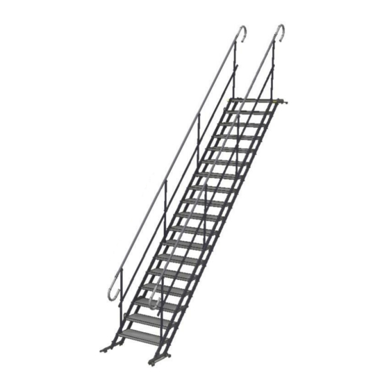
2. Components The basic TAS excavation stairs components are flights of stairs with railings. Flights are available in 3, 6, 9, 12,15, 18 step variants of 700 and 1000 mm width. The variants can be connected using proper connectors and supports. The system allows to establish a walkway over the obstacle with a platform and either 3- or 6- step flight. - Page 6 Stairs IDs (Sets of stairs with railings) Tab 1. Description TAS-3A Stairs with 3 steps, width 708 mm TAS-6A Stairs with 6 steps, width 708 mm TAS-9A Stairs with 9 steps, width 708 mm TAS-12A Stairs with 12 steps, width 708 mm...
- Page 7 TAS-S3B Weight: 40.6 kg TAS-BP3 Weight: 8.18 kg TAS-BL3 Weight: 8.18 kg...
- Page 8 TAS-S6A Weight: 53.26 kg TAS-S6B Weight: 71.86 kg TAS-BL6 Weight:10.96 kg...
- Page 9 TAS-BP6 Weight:10.96 kg TAS-S9A Weight: 76.45 kg TAS-S9B Weight: 104.4 kg...
- Page 10 TAS-BL9 Weight:15.1 kg TAS-BP9 Weight:15.1 kg TAS-S12A Weight: 98.18 kg...
- Page 11 TAS-S12B Weight: 135.5 kg TAS-BL12 Weight:17.9 kg TAS-BP12 Weight: 17.9 kg...
- Page 12 TAS-S15A Weight: 120.93 kg TAS-S15B Weight: 167.64 kg TAS-BL15 Weight: 20.67 kg...
- Page 13 TAS-BP15 Weight: 20.67 kg TAS-S18A Weight: 142.97 kg TAS-S18B Weight: 199 kg...
- Page 14 TAS-BL18 Weight: 24.81 kg TAS-BP18 Weight: 24.81 kg TAS-L5 Weight: 2.7 kg TAS-L6 Weight: 3 kg...
- Page 15 TAS-PR1 Weight: 10.28 kg TAS-K4 Weight: 50 kg...
- Page 16 TAS-K3 Weight: 45 kg TAS-PH3 Weight: 2.4 kg TAS-PR3 Weight: 1.6 kg...
- Page 17 D-TAS-064 Weight: 2.27 kg D-TAS-063 Weight: 0.2 kg TAS-WB1 Weight: 28.5 kg TAS-WB2 Weight: 8.9 kg...
- Page 18 TAS-WB3 Weight: 6.2 kg TAS-PR4 Weight: 1.6 kg TAS-L15 Weight: 1.3 kg...
- Page 19 TAS-L14 Weight: 1.3 kg TAS-L16 Weight: 2.1 kg TAS-L17 Weight: 2.1 kg TAS-BU Weight: 1.2 kg...
- Page 20 TAS-BL12H Weight: 16.5 kg TAS-BP12H Weight: 16.5 kg...
- Page 21 The list of fasteners Tab 3. TAS-3 TAS-6 TAS-9 TAS-12 TAS-15 TAS-18 Fasteners Quantity Bolt ISO 4762 8-ZN - M12 x 25 Nut ISO 4032 8-ZN - M12 Washer ISO 7089 ZN-12 - 200 HV Bolt ISO 7380 8-ZN M12 x 50 Nut ISO 10511 ZN - M12 Screw DIN 7504K 4,2x16 Galvanized Washer ISO 7089 ZN-8 - 200 HV...
- Page 22 Components required to create TAS-15 and TAS-18 stairs Tab 5. 15+15 15+18 18+18 Index/ Set TAS-15 A/B TAS-18 A/B TAS-WB1 TAS-WB2 TAS-WB3 Tab 6. MA torque for class 8.8 bolts Diameter Torque in Nm Approximate torque values for large thread bolts for friction coefficient μc = 0,15...
-
Page 23: List Of Tools Required For Tas Stairs Assembly
3. The list of tools required for stairs assembly List of tools Tab 7. Wrenches: 19, 18, 13, 10 Wrenches: 8, 10 Screwdriver Level Tape measure Lifter with at least 1 t capacity when assembling long sets... -
Page 24: Assembly Of Tas Stairs
4. Assembly of TAS stairs The method and the sequence of TAS stairs assembly are presented below: 4.1. Assembly of railings on stairs – insert railing posts into the holes in steps. 4.2. Tightening the railing lock – tighten the bolts (no.1) under the stairs inside the step holes... - Page 25 4.3. For 15- and 18-steps tighten the lock which is unlocked for transport. Unbolt the bolt (no.4) with the washer (no.3), insert into the other side of the lock (oblong hole), tighten it up. 4.4. In order to ensure the stiffness of the stairs, tighten up the bolts fixing the lock. Tighten the connection with 60% of torque intended for the diameter and class of the connector (see table 5.).
- Page 26 4.5. Connecting the stairs 4.5.1. Disassembly of railing ends – unbolt the screws that fix the ends of the railing on both sides of one end of the stairs. Disassemble a lower end in one flight of stairs, and upper end in the other one.
- Page 27 4.5.3. Assembly of a L5/L6 connector – spread the stairs and put one next to another, previously disassembling the foot. Unbolt the bolts fixing the last but one step, whose upper side is being connected with the last step of the second flight. Insert four L5 connectors into the stringer and tighten up all the bolt connectors (no.
- Page 28 4.6. Assembly of PR1 / PR4 supports – in case of the requirement to support the set of stairs, unbolt the bolt connections fixing the step (no. 3,4,5), put the fixing bracket that fastens the PR1 support, pass the bolt (4) with the washer (3) through the fixing bracket and fasten the nut (5).
- Page 29 4.7. Step-over platform assembly 4.7.1. Flight of stairs components disassembly: 1. Disassemble the upper foot (see 4.5.2) 2. Disassemble the upper end of the railing (see 4.5.1) 4.7.2. The handrail assembly- slide a handrail onto the railing ends and tighten up with screws.
- Page 30 4.7.3. Bar assembly – the bar is assembled to the stairs posts. 4.7.4. Toe board assembly – Fasten toe boards to D-TAS-063 and slide into the holes inside the platform.
- Page 31 4.8. Truss assembly 4.8.1. When assembling TAS-WB1 truss for 15 step stairs, TAS-L4 middle connectors should be disassembled. The truss is fastened with bolts used to assemble steps.
- Page 32 4.8.2. When assembling the truss for 18 step stairs, there is no need to disassemble TAS-L4 connectors. The TAS-WB1 truss is fastened with bolts used to assemble steps, TAS- WB2 component is fastened to TAS-WB1 with connectors included in the TAS-WB1 set.
- Page 33 4.8.3. When assembling two flights of stairs with a truss, they should be fastened at the base with connectors used to assemble steps, and at the upper part with the TAS-WB3 bar using connectors included in the bar set. Before connecting the stairs, disassemble the railings.
- Page 34 4.9. Assembly of pipe holders 4.9.1 To assemble the upper holder, disassemble the upper foot (see 4.5.2) and mount TAS-L15/ TAS-L14 holders with the same bolts. Prior to the assembly, the bolts on the lock must be loosened, the lock must be moved up, the holder is then placed and secured with the lock moved down again.
- Page 35 4.9.3 To assemble the lower holder, disassemble the lower foot (see 4.5.2) and assemble TAS-L16 / TAS-L17 holders using the same bolts. Prior to the assembly, loosen the screws on the foot that fasten the lock, move it up, place the holder and secure it with moving the lock down.
-
Page 36: Assemby Of Stairs And Gangways
5. Assembly of stairs and gangways The assembly should be conducted after earlier preparation of the ground, which means levelling and providing a stable support for the stairs during the entire exploitation process. Considering the temporary character of the construction, it is allowed to mount it on reinforced concrete slabs, concrete blocks or wooden blocks. - Page 37 Fig.3- Gangway made of 2 flights reinforced by a truss. Excavation depth [m] Distance from excavation edge [m] Fig. 4- Angle and distance from the edge. * gangway reinforced by a truss.
-
Page 38: Operational Conditions
The stairs should be assembled on excavation by at least two qualified specialists and a crane. Prior to the assembly, one should determine the assembly zone in such a way that it will not interfere with construction works and cause any danger. Determine the place of stairs assembly in such a way that it will not interfere with construction works and cause any danger Determine and prepare the zone where the stairs are to be placed on.
Need help?
Do you have a question about the TAS-3A and is the answer not in the manual?
Questions and answers