Table of Contents
Advertisement
Quick Links
Instruction Manual
Form 5302
April 2001
Design CV500 Rotary Control Valve
Contents
. . . . . . . . . . . . . . . . . . . . . . . . . . . . . . .
. . . . . . . . . . . . . . . . . . . . . . . . . . . . .
. . . . . . . . . . . . . . . . . . . . . . . . . . . . . . . . . .
. . . . . . . . . . . . . . . . . . . . . . . . . . . . . . .
. . . . . . . . . . . . . . . . . . . . . . . . . . . . . . . . .
. . . . . . . . . . . . . . . . . . . . . . . . . . . . . . .
. . . . . . . . . . . . . . . . . . . . . . . . . .
. . . . . . . . . . . . . . . . . . . . . . . . . .
. . . . . . . . . . . . . . . . . . . . . . . . . . . . . .
. . . . . . . . . . . . . . . . . . . . . . . . . . . . . . . . .
. . . . . . . . . . . . . . . . . . . . . . . . . . . . . .
. . . . . . . . . . . . . . . . . . . . . . . . . . . . . . . . .
. . . . . . . . . . . . . . . . . . . . . . . . . . . .
. . . . . . . . . . . . . . . . . . . . . . . . . . . . . . . . .
. . . . . . . . . . . . . . . . . . . . . . . . . . . . . . . . . .
Introduction
Scope of Manual
This instruction manual provides installation,
operation, maintenance, and parts ordering
information for 3- through 12-inch Design CV500 Cam
Vee-Ballr rotary control valves. Refer to separate
manuals for information concerning the actuator and
accessories.
. . . . . . . . . . . . . . . . . . . . . . . .
. . . . . . . . . . .
. . . . . . . . . . . . . . . . . . . .
. . . . . . . . . . . . . . .
. . . . . . . . . . . .
1
1
2
2
2
7
8
8
8
.
10
11
W8192 / IL
11
12
12
Figure 1. Design CV500 Flanged Valve with Type 1052
15
Actuator and Type DVC6020 Positioner
17
18
18
18
18
19
W5000-1 / IL
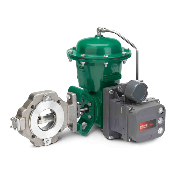
Figure 2. Design CV500 Wafer Valve with
Design CV500
Type 1066 Actuator
Advertisement
Table of Contents

Related Manuals for Fisher-Rosemount Design CV500

Summary of Contents for Fisher-Rosemount Design CV500
-
Page 1: Table Of Contents
......Figure 1. Design CV500 Flanged Valve with Type 1052 Assembly . -
Page 2: Description
The Design CV500 Cam-Vee-Ball rotary control valve, valve are listed in table 1. has a Vee-BallR style segmented ball in a valve body similar to the Design V500 valve. The Design CV500 is a flanged (figure 1) or wafer (figure 2) valve with a Installation patented, self-centering seat, eccentrically rotating V-notch ball, and splined valve shaft. - Page 3 When ordered, the valve configuration and construction materials were 3. A Design CV500 valve is normally shipped as part selected to meet particular pressure, of a control valve assembly, with a power or manual pressure drop, temperature, and actuator mounted on the valve.
- Page 4 WARNING For best shutoff performance, install the valve with the drive shaft horizontal and the Vee-Ball closing in the downward A Design CV500 drive shaft is not direction for standard right hand necessarily grounded when installed in a mounting. pipeline unless the shaft is electrically bonded to the valve.
- Page 5 Design CV500 ACTUATOR ACTUATOR POSITION VALVE OPEN MOUNTING STYLE STYLE A (PDTC) RIGHT HAND STYLE B (PDTO) STYLE C (PDTO) LEFT- HAND STYLE D (PDTC) NOTES: 1. ARROW ON LEVER INDICATES DIRECTION OF ACTUATOR THRUST TO CLOSE VALVE. 2. PDTC—PUSH DOWN TO CLOSE; PDTO—PUSH DOWN TO OPEN.
- Page 6 Design CV500 Line Studs (Key 36) Cap Screws (Key 37) Valve Valve Bolt Bolt Overall Size Size Bolt Size Bolt Size Length, Length, Length, PN 10-40 M16 x 2 PN 10-40 M16 x 2 PN63 M20 x 2.5 PN63 M20 x 2.5...
-
Page 7: Maintenance
Design CV500 Note ACTUATOR VALVE BODY Standard Design CV500 packings (key 13) are composed either entirely of conductive packing rings (graphite ribbon packing) or partially of conductive packing rings (a carbon-filled PTFE female adaptor with PTFE V-ring packing or a graphited-composition... -
Page 8: Packing Maintenance
Design CV500 Packing Maintenance 1. Isolate the control valve from the line pressure, release pressure from both sides of the valve body, Key numbers refer to figure 11 for 3 through 8-inch and drain the process media from both sides of the sizes and to figure 12 for 10 and 12-inch sizes unless valve. - Page 9 Design CV500 LEAKOFF ARRANGEMENT DOUBLE PACKING ARRANGEMENT BRAIDED PTFE COMPOSITION & GRAPHITE RIBBON DOUBLE PACKING ARRANGEMENTS PRESSURE VACUUM SERVICE PRESSURE SERVICE VACUUM SERVICE PTFE/V RING DOUBLE PACKING ARRANGEMENTS FOR PURGED BEARING FOR PURGED BEARING CONSTRUCTION CONSTRUCTION GRAPHITE RIBBON OR PTFE V RING...
-
Page 10: Replacing Retainer, Seat Ring, And Face Seals
Design CV500 C0774-1 / IL PTFE/COMPOSITION OR GRAPHITE ENVIRO SEAL PACKING ARRANGEMENTS Figure 6. Packing Arrangements (Continued) manual. Complete the Adjusting Actuator Travel actuator and valve must be removed from the pipeline; procedure in this manual before installing the valve in however, the actuator may remain mounted during this the pipeline. -
Page 11: Disassembly
Design CV500 the shutoff surface of the seat ring, and the face seal against ball travel by using travel stops, surface in the valve body. manual actuators, constant supply pressure to a pneumatic actuator, or A new retainer gasket (key 11) is required whenever other steps as appropriate. -
Page 12: Replacing Ball, Shaft, And Bearings
Design CV500 feeler gage to measure between the parts as shown in When the actuator is removed from the figures 11 and 12, making certain the necessary valve, the ball/shaft assembly may clearance exists. Compare the measured gap to the suddenly rotate, resulting in personal clearance in table 5;... - Page 13 Design CV500 VALVE SIZE (SQUARE) (SQUARE) Inches 79.2 33.3 41.4 19.0 3.12 1.31 1.62 104.6 33.3 41.4 25.4 4.12 1.31 1.62 1.00 155.4 38.1 11.2 63.5 11.2 25.4 6.12 1.50 2.50 1.00 203.2 50.8 11.2 101.6 11.2 38.1 8.00 2.00 4.00...
- Page 14 Design CV500 Table 6. Data for Tapped Holes on Valve Shaft SHAFT DIAMETER THREAD THREAD Through At Spline Through At Spline VALVE SIZE, Valve Valve SIZE SIZE Inches 25.4 25.4 1.00 1.00 3/8-16 25.4 19.1 1.00 0.75 5/16-18 DRIVE PINS OUT FROM THIS END 31.8...
-
Page 15: Assembly
Design CV500 A MAX. CAUTION VALVE MIN. SIZE SIZE Inches Inches To avoid damage to O-rings resulting 27.8 1.094 6.50 from contact with sharp edges within the 27.4 1.078 bearing holes, use appropriate care 34.1 1.344 6.50 when installing the O-rings. - Page 16 Design CV500 shaft until the slash mark is vertical and facing out PINS GO IN FROM THIS END (LARGER HOLE) from the center of the shaft in the same direction as the ball seating surface. See figure 10. Note When the valve drive shaft is correctly...
-
Page 17: Adjusting Actuator Travel
Design CV500 valve so that the of the smaller hole on the opposite side of the ball. ball is rotated to the fully closed position. A gap of Closely observe the progress of the pin to avoid approximately 0.001 inch (0.0254 mm) for... -
Page 18: Changing Valve Flow Direction
Repair Kits Repair kits include recommended spares for standard and sealed bearing constructions. Changing Valve Flow Direction The Design CV500 valve may be installed in either REPAIR KIT VALVE SIZE, INCHES forward or reverse flow service. Forward flow enters NUMBER the seat ring first, then flows past the V-notch ball. -
Page 19: Parts List
Design CV500 Retrofit Kits for ENVIRO-SEAL Packing Parts List Retrofit kits include parts to convert existing Design CV500 valves with single depth packing box to the Valve Body (figures 11 and 12) ENVIRO-SEAL packing box construction. Retrofit kits Body/Bearing Assembly... - Page 20 Design CV500 Description Part Number Description Part Number Packing Set, (cont’d) Packing Box Ring (cont’d) Packing set w/non-conductive V-ring S31603 (316L SST) 3-inch 12A8832X012 3-inch 16A6085X062 4-inch 12A8951X012 4-inch 16A6086X082 6- & 8-inch 12A8935X012 6- & 8-inch 16A6087X072 10-inch 12A9057X012...
- Page 21 Design CV500 TCM SEAL DOUBLE PACKING SEALED BEARING APPLY LUB KEY NUMBERS NOT SHOWN ARE 28, 30, 31, 33, 36, 37, 130, AND 131 NOTE: MEASURE GAP HERE 42B3374-A / IL Figure 11. 3 Through 8-Inch Design CV500 Valve...
- Page 22 Design CV500 DOUBLE PACKING SEALED BEARING APPLY LUB KEY NUMBERS NOT SHOWN ARE 28, 30, 31, 33, 36, 37, 130, AND 131 NOTE: MEASURE GAP HERE 42B5286-A / IL Figure 12. 10 and 12-Inch Design CV500 Valve...
- Page 23 Design CV500 42B8445-B SINGLE PTFE PACKING STANDARD DEPTH BOX 14B0095-A STACKING ORDER OF PTFE PACKING RINGS 42B8445-B 42B8445-B DOUBLE PTFE PACKING WITH LEAKOFF DOUBLE PTFE PACKING OPTIONAL DEEP PACKING BOX STANDARD DEPTH PACKING BOX NOTES: APPLY LUBRICANT. THESE TWO SURFACES SHOULD REMAIN PARALLEL AS YOU ALTERNATELY AND EVENLY TIGHTEN THE PACKING NUTS (KEY 101).
- Page 24 Design CV500 14B0086-A 42B8445-B STACKING ORDER OF GRAPHITE PACKING GRAPHITE PACKING RINGS STANDARD DEPTH BOX NOTES: APPLY LUBRICANT. THESE TWO SURFACES SHOULD REMAIN PARALLEL AS YOU ALTERNATELY AND EVENLY TIGHTEN THE PACKING NUTS (KEY 101). Figure 14. Typical ENVIRO-SEAL Rotary Packing Arrangements with Graphite Packing...
- Page 25 Design CV500 Key 4* Seat Ring—Full Port, Use w/Metal Seal Construction MATERIAL VALVE SIZE VALVE SIZE, CF8M CF3M R30006 CF8M CF3M INCHES (316 SST) (316L SST) (Alloy 6) w/CoCr-A Seat w/CoCr-A Seat 29A3703X012 29A3703X092 29A3703X022 - - - - - -...
- Page 26 Design CV500...
- Page 27 Design CV500...
- Page 28 Design CV500 ENVIRO-SEAL, Cam Vee-Ball, Vee-Ball, edisc, Fisher and Fisher-Rosemount are marks owned by Fisher Controls International, Inc. or Fisher-Rosemount Systems, Inc. All other marks are the property of their respective owners. This product may be covered by one or more of the following patents: 4,519,579; 5,016,857; 5,129,625; 5,131,666; 5,542,681 or under pending patents.
Need help?
Do you have a question about the Design CV500 and is the answer not in the manual?
Questions and answers