Table of Contents
Advertisement
Quick Links
Instruction Manual
Form 5456
November 1998
Posi-Seal Type A31A High Performance
Butterfly Valve 3 through 12-Inch
Contents
. . . . . . . . . . . . . . . . . . . . . . . . . . . . . .
. . . . . . . . . . . . . . . . . . . . . . . . . . . . .
. . . . . . . . . . . . . . . . . . . . . . . . . . . . . . .
. . . . . . . . . . . . . . . . . . . . . . . . . . . . . . . . . .
. . . . . . . . . . . . . . . . . . . . . . . . . . . . . . . .
. . . . . . . . . . . . . . . . . . . . . . . . . . . . .
. . . . . . . . . . . . . . . . . . . . . . . . . . . . . .
. . . . . . . . . . . . . . . . . . . . . . . . . . .
. . . . . . . . . . . . . . . . . . . . . . . . . . . . .
. . . . . . . . . . . . . . . . . . . . . . . . . . . . . . . . .
. . . . . . . . . . . . . . . . . . . . . . . . . . .
. . . . . . . . . . . . . . . . . . . . . . . . . . .
Introduction
Scope of Manual
This instruction manual provides installation, mainte-
nance, and parts ordering information for the
POSI-SEAL Type A31A high-performance butterfly
. . . .
. . . . . . . . . . . . . . . . . . . . . .
. . . . . . . . . . . . . . . . . . .
. . . . . . . . . . . . . . . . .
. . . . . . . . .
10
. . . . . . . . . . . .
11
. . . . . . . . . . . . . . . . . . . . .
11
. . . . . . . . . . . . . . . .
12
. . . . . . . . . . . . . . . . .
13
14
14
. . . . . . . . . . . . . . . .
16
. . . . . . . . . . . . . . . .
16
. . . . . . . . . . . . . . .
17
18
18
1
1
2
1
2
W5811-1/IL
3
3
4
7
8
9
9
W5812-1/IL
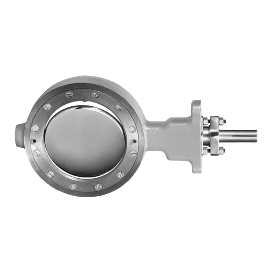
Figure 1. Typical Type A31A Valve
valves. Figure 1 shows typical Type A31A valves. For
information regarding actuators and accessories, refer
to separate instruction manuals.
Only personnel qualified through training or experience
should install, operate, and maintain this valve. If you
have any questions concerning these instructions,
contact your Fisher Controls sales representative or
sales office before proceeding.
Description
The Type A31A high-performance butterfly valve fea-
tures a keyed drive shaft. The keyed shaft combines
with a variety of handlevers, handwheels, pneumatic
piston or spring-and-diaphragm actuators to make the
Type A31A a reliable, high-performance, butterfly
valve for a variety of applications in the various pro-
cess industries.
Type A31A
Advertisement
Table of Contents

Related Manuals for Fisher-Rosemount Posi-Seal A31

Summary of Contents for Fisher-Rosemount Posi-Seal A31
-
Page 1: Table Of Contents
Instruction Manual Form 5456 Type A31A November 1998 Posi-Seal Type A31A High Performance Butterfly Valve 3 through 12-Inch Contents Introduction ......Scope of Manual . -
Page 2: Specifications
Type A31A Table 1. Specifications Available Valve Configurations Valve Classification Face-to-face dimensions are in compliance with Flangeless, wafer-style or single-flange MSS SP68 and API 609 standards; valve bodies (lugged) control valve with a one-piece valve body are designed for installation between ASME B16.5 and a two-component seal/backup O-ring, and a Class 150 or 300 raised-face flanges keyed drive shaft... -
Page 3: Adjusting The Actuator Travel Stops Or Travel
Type A31A Adjusting the Actuator Travel Stops Table 2. Material Temperature Ratings TEMPERATURE RANGE COMPONENT, ANSI CLASS, COMPONENT, ANSI CLASS, MATERIAL OF CONSTRUCTION WARNING Seal Ring See Figure 2 Backup Ring The edges of a rotating valve disk have Soft Seal Fluoroelastomer -20 to 400 -29 to 204... -
Page 4: Preparing For Installation
Type A31A Table 3. Valve Body Data, Class 150 Table 4. Valve Body Data, Class 300 SHAFT FACE-TO- SHAFT FACE-TO- MINI- APPROX. MINI- APPROX. DIA. FACE DIA. FACE WEIGHT, WEIGHT, VALVE VALVE AT YOKE DIMEN- AT YOKE DIMEN- .(2) .(2) POUNDS POUNDS SIZE,... - Page 5 Type A31A B2335–2/IL Figure 2. Maximum Pressure/Temperature Ratings...
- Page 6 Type A31A B2336-1 / IL Figure 2. Maximum Pressure/Temperature Ratings (continued)
-
Page 7: Installing Wafer-Style Valves
Type A31A B2334–1/IL Figure 3. Available Seal Configurations certain that adjacent pipelines are free of any foreign Installing Wafer-Style Valves material, such as pipe scale or welding slag that could damage the valve seating surfaces. WARNING The edges of a rotating valve disk have CAUTION a shearing effect that may result in per- sonal injury. -
Page 8: Installing Single-Flange Valves
Type A31A Table 5. Hex Head Screw, Stud Bolt and Cap Screw Data ACTUATOR VALVE BODY SIZE DIA. INCH & NUMBER LENGTH, INCH VALVE THREAD SIZE SIZE, Class Class Class Class Class Class INCH Single-Flange Style with Stud Bolts 5/8-11 3/4-10 5-3/4 5/8-11... -
Page 9: Maintenance
Type A31A Table 6. Torque Values for Fasteners FASTENER NOMINAL SIZE 5/16 7/16 9/16 1-1/8 Lbf in Lbf ft Retaining Retaining 1000 Ring Ring Screws 1356 Lbf in Lbf ft Gasket Retaining Retaining Bolts Bolts Nore: These values are based upon standard materials, S66286/Inconel screws and ASTM A193GRB6 bolts. For other special fasterer materials, please contact your Fisher Controls sales office or sales representative. -
Page 10: Removing The Valve From The Pipeline
Type A31A For valves using the ENVIRO-SEAL packing CAUTION system: Normally, the packing nuts should not require re-tight- Tighten the packing flange only enough ening. However, when servicing an ENVIRO-SEAL to prevent shaft leakage. Excessive packing system, if the springs do not remain nearly tightening will only accelerate wear of flat, retighten the packing box nuts until the springs the packing and could produce higher... -
Page 11: Removing/Installing The Seal Ring
Type A31A 4. Insert a regular screw driver or other similar tool CAUTION under the top edge of the seal ring (key 5), and gently pry it out of the T-slot area in the valve body. Take care not to damage the seal ring or T-slot area of the Damage to the valve disk, piping or pipe valve body. -
Page 12: Novex Seal And Phoenix Iii Fire-Tested Seal Installation
Type A31A Novex Seal and Phoenix III Fire-Tested Seal Installation Unless otherwise indicated, key numbers and part names are listed in figure 8. A maintenance kit with installation tools is available through your Fisher Controls representative or sales office. 1. Locate the replacement seal ring (key 5) and note the shape of the ring. -
Page 13: Cryogenic Seal Installation
Type A31A 12. Use an appropriate tool (such as a feeler gauge) WARNING and position the disk from 0.001 to 0.030 inch (0.03 to 0.76 mm) away from the internal stop in the valve body. Avoid personal injury or property dam- age caused by the impact of a falling or This adjustment is necessary to be certain that the tipping valve. -
Page 14: Anti-Blowout Protection, Packing, Valve Shaft(S), Disk, And Bearing Maintenance
Type A31A C0766 / IL Figure 7. Anti-Blowout Protection Detail Anti-Blowout Protection, Packing, Valve valve shaft. It is okay to tap the wheel puller screw lightly to loosen the lever Shaft(s), Disk, and Bearing Maintenance or actuator, but hitting the screw with excessive force could also damage in- Note ternal valve parts. - Page 15 Type A31A Note For valves with tangential pins and/or disk pins, locate the tangential pins (key 26) in the drive shaft 3- through 12-inch valve sizes (classes (key 3) and the disk pin (key 26) in the follower shaft 150 and 300) have a bearing stop (key 8, (key 4).
-
Page 16: Installing A One-Piece Shaft
Type A31A bore. Do not attempt to remove the bearing stop when driving the key or pins into the (key 8). Remove the journal bearing from the follower disk hub and shaft(s). Use the right tool. shaft bearing bore. Do not use excessive force. 12. -
Page 17: Installing The Gasket Retainer
Type A31A when driving the key or pins into the CAUTION disk hub and shaft(s). Use the correct tool, and do not use excessive force. Premature valve failure and loss of pro- 10. Before installing the taper key, be sure the taper cess control may result if bearings are key disk shaft joint is free of oil or grease. -
Page 18: Parts Ordering
Type A31A 3. Be sure to center the gasket over the follower shaft Description bore before retightening the bolts. Tighten down the JOURNAL BEARING bolts evenly in a crossover or star pattern. Refer to BEARING STOP table 6 for proper torque values. ANTI-BLOWOUT FLANGE PACKING FLANGE PACKING FOLLOWER... - Page 19 Type A31A A5947/IL 27291 (WAFER STYLE SHOWN) 27301 C0821 / IL Figure 8. Type A31A 3 through 12-inch Typical Assembly...
- Page 20 Type A31A Posi-Seal, Phoenix III, ENVIRO-SEAL, NOVEX, Fisher, Fisher-Rosemount, and Managing The Process Better are marks owned by Fisher Controls International, Inc. or Fisher-Rose- mount Systems, Inc. All other marks are the property of their respective owners. Fisher Controls International, Inc. 1998; All Rights Reserved...
Need help?
Do you have a question about the Posi-Seal A31 and is the answer not in the manual?
Questions and answers