Advertisement
1. CONTENTS.
Page
Section
1
1. Contents
2
3
4
5
6
7
8-10
11-13
7. Spare Parts -
T.L.
Issue
G
NOV-20
AR7187 ISSUE G
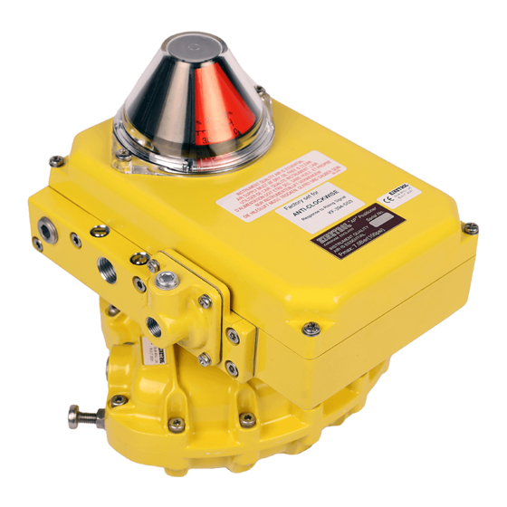
Title: Installation & Maintenance - AP Pneumatic Positioner
2.1 Direct Mounting Units onto Kinetrol Positioner
Actuators
2.2 Mounting of Discrete Positioners.
2.3 Air and Electrical Connections.
4.1 Change of Direction for rising signal (direct mounted)
4.2 Zero and Range Adjustment
4.3 Speed Control
4.4 Change of Direction for rising signal (Discrete)
6.1 Installation
6.2 Change of Direction for rising signal
6.3 Zero and Range Adjustment
6.4 Change of Direction for rising signal (Discrete)
6.5 Change of Angle Retransmit direction without
changing positioner direction.
6.6 Angles of less than 0º to 90º
7.1 Exploded View
Trading Estate Farnham Surrey England
Doc. No.TD 106
Page 1 of 13
TD106 - 11/08:INDEX H\Drawing office docs. Master KF WI TD etc.\current TD sheet
masters
KF 399
Advertisement

Related Manuals for Kinetrol AP

Summary of Contents for Kinetrol AP
-
Page 1: Table Of Contents
Title: Installation & Maintenance – AP Pneumatic Positioner 1. CONTENTS. Page Section 1. Contents 2.1 Direct Mounting Units onto Kinetrol Positioner 2. Installation - Actuators 2.2 Mounting of Discrete Positioners. 2.3 Air and Electrical Connections. 3. Description of Operation 4. Settings and Adjustments –... -
Page 2: Installation
(discrete) form for fitting via a mount kit to any 90 degree rotary or linear actuator. If the positioner is supplied ready mounted on an actuator, sections 2.1 & 2.2 can be bypassed. Positioner-type Kinetrol actuators (ready for direct mount of positioners) are available in models 050 to 140 inclusive. - Page 3 2.3.3 External Actuator Ports. For positioners not fitted directly onto Kinetrol Positioner type Actuators, two external ports are provided for connecting the positioner outlets to the actuator. The size of the ports is dependant on the positioner ordering code. These ports can also be used for fitting pressure gauges if desired.
-
Page 4: Description Of Operation
Kinetrol actuators. The feedback cam is retained by a coupling which, in the case of a Kinetrol direct mounted positioner, is held onto the vane square by a collet. For discrete versions, the coupling is retained in bearings and connected by either a male square or 'Namur' style connector. -
Page 5: Settings And Adjustments
Title: Installation & Maintenance – AP Pneumatic Positioner 4. SETTINGS AND ADJUSTMENTS. The positioner will have been factory set to the requirements given in the ordering code ( i.e. the direction of rotation for a rising pressure signal and the range and zero settings). However, if these settings need to be changed, the following section describes the procedure for achieving this. - Page 6 'HP'. This method, however, not only effects the actuator speed but also effects the 'gain' and therefore control stability of the unit and care must be taken not to specify a too high flow valve for a given size of actuator. Kinetrol Ltd has recommendations (shown in the AP literature) for each size of the actuator b.) adjustment of the built in flow restrictors (shown in Figure 4) is achieved using a screwdriver.
-
Page 7: Maintenance And Troubleshooting
Title: Installation & Maintenance – AP Pneumatic Positioner 5. MAINTENANCE AND TROUBLESHOOTING. The AP positioner is designed for a long life with very little maintenance required if it is supplied with clean, dry oil free air, as recommended in section 2.3. -
Page 8: Angle Retransmit Option
Title: Installation & Maintenance – AP Pneumatic Positioner 6. ANGLE RETRANSMIT OPTION. 6.1.1 Move actuator vane to mid travel position, with its output square as shown in Figure 1. This is advisable to prevent subsequent error in orientating positioner coupling. (This is not necessary with spring return actuators as there can be no confusion with square orientation). - Page 9 Title: Installation & Maintenance – AP Pneumatic Positioner 6.2.4 Pull the two halves of the coupling apart sufficiently to allow the cam to be withdrawn from its location peg. Flip the cam over and push it back into the slot between the two coupling halves and locate it back on the peg.
- Page 10 Title: Installation & Maintenance – AP Pneumatic Positioner 6.4.6 If when the coupling was removed, the collet was left behind on the actuator connection, remove the collet from the connection and push it into the lower half of the coupling ensuring that it locates in the semicircular 'pip' and tighten the clamping screw by two turns.
- Page 11 Title: Installation & Maintenance – AP Pneumatic Positioner T.L. Doc. No. TD 106 Issue Trading Estate Farnham Surrey England Page 11 of 13 NOV-20 AR7187 ISSUE G...
-
Page 12: Spare Part Numbers
Title: Installation & Maintenance – AP Pneumatic Positioner ITEM SPARES PART NUMBER DESCRIPTION 10 / 12 / 14 16/18/20/30 Cover Assembly - standard* SP1200 SP1200 SP1200 SP1200 SP1200 Cover Assembly – for switch box* SP1201 SP1201 SP1201 SP1201 SP1201 Cover Seal & Grease - NBR... - Page 13 Title: Installation & Maintenance – AP Pneumatic Positioner ITEM DESCRIPTION SPARES PART NUMBER 10 / 12 / 14 16/18/20/30 Coupling SP1253 SP1254 SP1254 SP1254 SP1253 Discrete Coupling SP1253 SP1253 SP1253 SP1253 SP1253 Discrete Drive Adaptor - Kinetrol SP1601 SP1601 SP1601...
Need help?
Do you have a question about the AP and is the answer not in the manual?
Questions and answers