Advertisement
Available languages
Available languages
Quick Links
Curtarolo (Padova) Italy
www.avselectronics.com
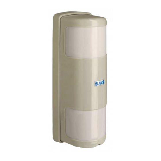
SPIDER P
SPIDER P A A A A A
SPIDER P
SPIDER P
SPIDER P
SPIDER P A A A A A WS
SPIDER P
SPIDER P
SPIDER P
SPIDER P
Sensore a doppio infrarosso passivo
da esterno e interno
SPIDER DU
SPIDER DU
SPIDER DU
SPIDER DU AL
SPIDER DU
Sensore a microonda e doppio infrarosso
passivo da esterno e interno
IST0505V3.5
- 1 -
AZIENDA CON SISTEMA
QUALITA' CERTIFICATO
ISO 9001
WS
WS
WS
WS
AL
AL
AL
AL
I
T
A
E
N
G
Advertisement

Related Manuals for AVS Electronics SPIDER PA


Summary of Contents for AVS Electronics SPIDER PA
- Page 1 AZIENDA CON SISTEMA QUALITA’ CERTIFICATO ISO 9001 Curtarolo (Padova) Italy www.avselectronics.com SPIDER P SPIDER P A A A A A SPIDER P SPIDER P SPIDER P SPIDER P SPIDER P A A A A A WS SPIDER P SPIDER P SPIDER P Sensore a doppio infrarosso passivo da esterno e interno...
-
Page 2: Sistemi Di Sicurezza
SPIDER PA WS è dotato di un circui- un’analisi dei segnali e li gesti- ( SPIDER PA - SPIDER DUAL ) sce in base alla modalità di fun- to che ne regola automaticamente la sce in base alla modalità... - Page 3 Composizione sensore PASSACAVO PIASTRA A MEMBRANA BASE COPERCHIO SCHEDA ELETTRONICA SPIDER PA WS MODULO TAMPER DATI TARGA VITE DI VITE DI FISSAGGIO FISSAGGIO SCHEDA BASE CON TAMPER GUARNIZIONE SCHEDA SCHEDA ELETTRONICA ELETTRONICA VITE DI SPIDER PA SPIDER DUAL FISSAGGIO ! ATTENZIONE !
- Page 4 Apertura sensore Montaggio della piastra a muro Montaggio della piastra a palo Per l’installazione della vite di Per l’installazione della vite di riferimento antistrappo, se- riferimento antistrappo, se- Sfilare il coperchio. guire le istruzioni a pagina 5. guire le istruzioni a pagina 5. Con il kit opzionale (KIT SP) per l’in- stallazione a palo, fissare i supporti ad anello alla piastra (con viti M4 x 10...
- Page 5 Vite riferimento antistrappo Passaggio cavo SPIDER PA e SPIDER DUAL Se l’entrata del cavo è dal fondo del sensore, utilizzare il foro cen- trale nella piastra (come indicato nella figura a sinistra). Utilizzare, per la vite di riferimen- to dell’antistrappo, il distanziatore in dotazione.
- Page 6 ATTENZIONE e poi quello superiore) nelle per non viene utilizzato, to in figura e posizionare la batteria Nei modelli SPIDER PA e SPIDER proprie sedi, avendo cura di man- ponticellare i morsetti TT sulla base fissandola con il DUAL, la mancata applicazione del tenere la morsettiera a destra.
- Page 7 Segnalazioni SPIDER PA Segnalazioni SPIDER PA WS Segnalazioni SPIDER DUAL SPIDER PA è dotato di un buzzer e di un SPIDER PA WS è dotato di un buzzer e SPIDER DUAL è dotato di un buzzer e di led per dare una segnalazione ottico-acu-...
- Page 8 CERTIFICAZIONE IMQ sto morsetto e un negativo, si ha la segnalazione di allarme solo con la rilevazione sia dello SPIDER PA che del sensore Chiuso Reset microprocessore esterno collegato ( DIP3 ).
- Page 9 Spider PA genera allarme solo se rileva un’intrusione e, con- (default) temporaneamente, è aperto l’ingresso AUX. N.B. Per il corretto funzionamento del sensore SPIDER PA, senza l’utilizzo del contatto supplementare, il morsetto AUX deve risultare aperto (default). DIP 4 - CONTATTO ALLARME (default) Contatto d’allarme senza resistenza.
- Page 10 Morsettiera SPIDER PA WS Jumper SPIDER PA WS TAMPER Sulla scheda sono pre- senti due morsetti (T T - TAMPER) per la segnala- zione di manomissione, da collegare al modulo tamper in dotazione al sensore. Se non vengono utilizzati devono essere ponticellati c r i tra di loro.
- Page 11 Basso consumo: dopo aver rilevato e trasmesso un allarme, t l u SPIDER PA WS rimane inibito. Solo dopo 3 minuti senza aver i t u rilevato allarmi, riprende il suo funzionamento normale. ! ATTENZIONE ! Con l’integrazione, SPI-...
- Page 12 Morsettiera SPIDER DUAL Positivo alimentazione 12 V La morsettiera è posta sul lato Negativo alimentazione 12 V inferiore della scheda, nel punto indicato in figura. Ingresso che permette al sensore di avere il riferimento del- lo stato della centrale. A centrale spenta questo ingresso deve risultare chiuso a positivo, in questa condizione il sensore si comporta come segue: •...
- Page 13 Jumper e Trimmer l l a i t t SPIDER DUAL l l a i t t l l a l l a è l è l c r i o l l i l i o l l i l i a l l i l a à...
- Page 14 14 m La zona superiore rileva parallelamente al NOTA 1 SPIDER PA WS: queste portate si ottengono con i jumper S1 terreno e non può essere orientata. e S2 impostati su MAX (vedi capitolo Jumper SPIDER PA WS) .
- Page 15 Portata sensore SPIDER PA : per ridurre le probabilità di avere false rilevazioni, diminuire la portata del sensore regolando la lente del pir inferiore. SPIDER PA WS : per ridurre la probabilità di false segnalazioni, regolare la portata agendo sui Jumper S1 e S2.
- Page 16 • Il raggio parallelo al terreno si riferisce allo specchio superiore e non Portata può essere regolato. • Il raggio inferiore nelle figure, si riferisce alle tre possibili regolazioni SPIDER DUAL La regolazione ottimale della portata, si ha dello specchio inferiore. installando SPIDER DUAL perpendicolar- •...
- Page 17 90° Per posizionare il sensore nella direzione desi- derata, impugnare la scheda nella parte cen- trale (altezza morsettiera per SPIDER PA SPIDER DUAL e altezza batteria per SPI- DER PA WS) . Nell’asse di rotazione ci sono sette possibili posizioni di 15°...
- Page 18 La rilevazione di entrambe le sezioni genera l’allarme. La rilevazione della sola sezione superiore NON genera l’allarme (ad eccezione della modalità SECURITY per SPIDER PA). La rilevazione della sola sezione inferiore NON genera l’allarme (ad eccezione della modalità SECURITY per SPIDER PA).
- Page 19 Mascheramento Per ridurre l’angolo di coper- tura, o mascherare una Tagliare, in ambedue i filtri, le aree zona specifica , si possono di mascheramento evidenziate, utilizzare i filtri prefustellati per creare la finestra di rilevazio- in dotazione al sensore. ne selezionata. Il filtro è...
- Page 20 Accessori per l’installazione a palo Tramite l’ingresso AUX, è possibile gestire in AND o AND DIREZIONALE l’allarme di SPIDER PA e di un sensore esterno. Per la selezione della modalità, vedere DIP 3 al capitolo Dip Switch SPIDER PA. Nello stato di riposo, l’ingresso AUX deve risultare chiuso E’...
- Page 21 Installazioni errate SPIDER è protetto contro interferenze lu- minose. I raggi solari o forti fasci di luce che colpiscono direttamente gli specchi, potreb- bero creare delle condizioni instabili di fun- zionamento. Il raggio superiore deve risultare parallelo al terreno. Non ci devono essere corpi oscillanti all’interno del raggio di copertura.
- Page 22 1999/5/CEE (R&TTE) sugli apparati radiotrasmittenti di debole potenza e sull’uso delle frequenze dello spettro radioelettrico, in accordo anche con la raccomandazione CEPT 70-03. Marca AVS ELECTRONICS Modello SPIDER PA WS Frequenza di lavoro 868,350Mhz Tipo di alimentazione Batteria al litio Tensione nominale 3.6 V...
- Page 23 Il prodotto oggetto della presente dichiarazione è conforme alle prescrizioni fondamentali della Diretti- va 1999/5/CEE (R&TTE) sugli apparati radiotrasmittenti di debole potenza e sull’uso delle frequenze dello spettro radioelettrico, in accordo anche con la raccomandazione CEPT 70-03. Marca AVS ELECTRONICS Modello SPIDER DUAL Frequenza di lavoro...
- Page 24 ° 2 o l l ° 2 o l l AVS ELECTRONICS S.p.a. si riserva il diritto di apportare modifiche in qualsiasi momento e senza preavviso. - 24 -...
- Page 25 CERTIFIED QUALITY SYSTEM ISO9001 Curtarolo (Padova) Italy www.avselectronics.com SPIDER P SPIDER P A A A A A SPIDER P SPIDER P SPIDER P SPIDER P SPIDER P A A A A A WS SPIDER P SPIDER P SPIDER P Outdoor-Indoor dual passive infrared detector SPIDER DUAL SPIDER DUAL...
-
Page 26: General Characteristics
At first supplying, SPIDER PA WS w SPIDER PA is equipped with a w SPIDER PA WS is supplied by a 3.6 V outdoor protection remains inhibited for about 2 minutes. microprocessor which analyzes... -
Page 27: Pay Attention
Description FAIR-LEAD BACKPLATE BASE COVER SPIDER PA WS ELECTRONIC BOARD TAMPER BOARD LABEL DATA TAMPER BASE LOCK SCREW LOCK WITH RING SCREW SPIDER PA SPIDER DUAL ELECTRONIC ELECTRONIC COVER LOCK BOARD BOARD !! PAY ATTENTION !! SCREW INSTALLATION AND MAINTENANCE MUST... - Page 28 To open Spider Back plate Wall Mounting Back plate post Mounting To install the removable To install the removable tamper kit, see instructions tamper kit, see instructions Remove the cover on page n.5.. on page n.5.. CWith post mounting optional kit (KIT SP) fix the post bracket to the back plate using M4 x10 screws (side figure)
- Page 29 Removable tamper screw Wiring hole SPIDER PA and SPIDER DUAL If the wiring inlet is from the back of the detector, use the central hole on the back plate. (left picture). To mount the detector use, for the removable tamper screw, the spacer ring.
- Page 30 With regard to the models SPIDER PA tape given within. and SPIDER DUAL, failing to use the anti-tamper device will cause the IMQ certifiction to decade.
- Page 31 SPIDER PA Signalling SPIDER PA WS Signalling SPIDER DUAL Signalling SPIDER PA have a buzzer and a Led for SPIDER PA WS is equipped with a buzzer SPIDER DUAL is equipped with a buzzer and visual-acoustic signalling (Walk Test) and a Led to give out an optical-acoustic a Red Led in order to give an optical-acoustic even if the detector is blocked using B.
- Page 32 Terminals SPIDER PA Jumper SPIDER PA Pos. B Pos. A Positive power input 12 V Negative power input12 V Positive input to detect when the control unit is armed. Default When the control unit is disarmed input B must be closed to a positive;...
- Page 33 Hight detection sensitivity. Sensitivity is like Normal but with single pulse HIGH count. SECURITY Spider PA operates as Normal mode, but an alarm is also send when a single PIR section gives 3 consecutive alarms within 30 seconds. DIP 3 - AUX INPUT DIRECTIONAL AND...
- Page 34 SPIDER PA WS Terminals SPIDER PA WS Jumper TAMPER On the electronic board there are two terminals (T T - TAMPER) The two terminals on the board are used for tamper signalling, they must be connected to the tamper module given within the detector.
- Page 35 Low consumption: after detecting and sending an alarm, t l u SPIDER PA WS remains inhibited. Only after 3 minutes with no alarms detected, it starts again to work as usual. !! PAY ATTENTION !!
- Page 36 SPIDER DUAL Terminals Supplying positive 12 V The terminal board is placed on the Supplying negative 12 V bottom side of the circuit as shown in the picture. Input which allows the detector to know the control unit condition. At disarmed system this input must be closed to positive, in this condition the detector behaves as follows: •...
- Page 37 SPIDER DUAL i t c Jumper / Trimmer i t c l l i f i t c r i t i u o l l - i t i t c o l l - i t i t c t l u v i t y t i...
- Page 38 S2 set on MAX (see chapter Jumper SPIDER PA WS). The lower side mirror can be inclined downward to adjust maximum detection NOTE 2 SPIDER PA WS: in order to reduce max range, refer to the chart shown on chapter Jumper SPIDER PA WS. range.
- Page 39 Detection range SPIDER PA: to reduce the risk of false detections, decrease the range of detector adjusting the mirror of lower pir. SPIDER PA WS: to reduce risk of false signalling, adjust the range acting on Jumper S1 and S2.
- Page 40 • The ray parallel to the ground is referred to the top mirror and cannot be SPIDER DUAL adjusted • The lower ray shown in the picture, is referred to three possible adjustings Detection To obtain the best adjusting of the range, of the lower mirror.
- Page 41 14mt over 90° (see figure) 90° To rotate SPIDER PA / SPIDER DUAL the orientation, hold the electronic board near the terminals, or near the battery for SPIDER PA The electronic board can be oriented at 7 different azimut angles with 15°...
- Page 42 Warning At the power up SPIDER PA is in stand by mode for 30 seconds. Testing the detector is possible after this warm-up period. Remember: To optmize the detection pattern and to obtain the wished protection area, follow the steps at pag.11 (Detection range), pag.10 (Detection Area) and pag.
- Page 43 Area Masking To reduce the detection angle, or to mask a zone, Cut the masking segments use the masking foil marked in the previous step to enclosed. obtain the selected detection angle. The foil is cutted in 12 masking segments of 15°...
- Page 44 AND Moder forSPIDER PA Post Mount accessories Using the AUX input, it is possible to set SPIDER PA to operate in AND o DIRECTIONAL AND combination with another detector. To activate the AND mode, look at pag.9 (DIP 3). The input AUX must be closed to negative, when the To mount SPIDER PA second detector is not in alarm.
- Page 45 Wrong Installation SPIDER PA is protected against any light disturbances. However, too strong light or sunlight, directed or reflected exactly into the sensor’s field of view, may cause unstable condition. The upper finger have to stay parallel to the ground...
- Page 46 Product mentioned in this statement is conform to basic indications of directive 1999/5/CE (R&TTE) on low-power radio-transmitting devices and on use of frequencies of the radio-electrical spectrum, in accordance with CEPT 70-03 Trade Mark AVS ELECTRONICS Model SPIDER PA WS Working frequency 868,350Mhz Supplying litium battery Nominal tension 3.6 V...
- Page 47 Product mentioned in this statement is conform to basic indications of directive 1999/5/CE (R&TTE) on low-power radio-transmitting devices and on use of frequencies of the radio-electrical spectrum, in accordance with CEPT 70-03 Trade Mark AVS ELECTRONICS Model SPIDER DUAL Working frequency...
- Page 48 (ref. EN ° 2 ° 2 60950) AVS ELECTRONICS S.p.A. reserves the right to modify the technical and esthetical characteristic of the products at any time. - 48 -...
Need help?
Do you have a question about the SPIDER PA and is the answer not in the manual?
Questions and answers