Table of Contents
Advertisement
Quick Links
Advertisement
Table of Contents

Related Manuals for SAF Spectrum Compact


Summary of Contents for SAF Spectrum Compact
- Page 1 Spectrum Compact 2-40 GHz STEP-BY-STEP GUIDE...
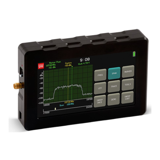
- Page 2 What is Spectrum Compact? The Spectrum Compact is an ultra-light and easy to use measurement solution. It operates in the 2 – 40 GHz frequency range. Designed specifically for comfortable outdoor use, this battery-powered device is a must-have tool for any microwave radio engineer performing link installations or gathering data for site planning purposes.
- Page 3 Spectrum Compact kit Additional accessories: includes: Riflescope, tripod and case for Spectrum Compact 2–8 GHz sniffer antennas Spectrum Compact 5.925–12 GHz Attenuator kit, 20–60dB Spectrum Compact 10–18 GHz Handheld horn antennas: Spectrum Compact 17–24.3 GHz 6.0-10.0 GHz Spectrum Compact 24–40 GHz Gain: 14.5-18.0dBi...
-
Page 4: Table Of Contents
Contents Short guide to using Spectrum Compact Spectrum Manager Equipment & general instructions Spectrum Compact Applications: Site survey Line of Sight (LoS) verification with SG Compact Spectrum investigation for possible free channels Confirmation of dedicated radio channel availability and status Spectrum Compact Applications: Radio link &... - Page 5 Spectrum Compact Applications: Basic trouble-shooting Verification of far end radio configuration Verification of antenna alignment and LoS Verification of antenna alignment using reference antenna Interference detection Multipath detection Annex Power ratio and decibel conversion table A simplified formula for path calculation...
-
Page 6: Short Guide To Using Spectrum Compact
SHORT GUIDE TO USING SPECTRUM COMPACT... - Page 7 To turn on the Spectrum Compact, slide the power switch at the top of the device towards the red dot (•). Operation time with a fully charged battery is up to 3 hours for the 24-40 GHz model, and up to 4 hours for all other models.
- Page 8 RECORD - this function continuously records every scan performed for later analysis ABOUT – access information about Spectrum Compact (supported frequency range, serial number, firmware version etc.) POWER IN BAND – set up an input power measurement for a selected bandwidth SIGNAL ID –...
-
Page 9: Spectrum Manager
Spectrum Manager is a spectrum analysis PC software for SAF Tehnika’s Spectrum Compact. In addition to managing firmware updates, Spectrum Manager can be used in both real-time (together with a Spectrum Compact device) and offline modes, and provides you with a variety of functions, such as: PiB (Power in Band), overlay and min/max hold. -
Page 10: Equipment & General Instructions
EQUIPMENT & GENERAL INSTRUCTIONS... - Page 11 Spectrum Compact Signal Generator...
- Page 12 Coaxial cable Waveguide adapter Attenuators...
- Page 13 In this position, the waveguide adapter detects horizontal polarization In this position, the waveguide adapter detects vertical polarization...
-
Page 14: Spectrum Compact Applications: Site Survey
SPECTRUM COMPACT APPLICATIONS: SITE SURVEY... -
Page 15: Line Of Sight (Los) Verification With Sg Compact
9. Set the chosen frequency and power. At the second site: Do the steps 2. - 6. at the second site. Make sure that both antennas are installed in the same polarization! 10. Connect Spectrum Compact to the antenna. Use appropriate attenuation! (see: General instructions) - Page 16 12. Tap SPAN, then FULL SPAN. Tap HOME. 13. Check for OVERLOAD: a) If there is an indication above the graph, remove Spectrum Compact from the antenna and add attenuators. b) If there is no indication above the graph, proceed with the next steps.
-
Page 17: Spectrum Investigation For Possible Free Channels
2. Climb the tower. 3. Connect Spectrum Compact to the handheld antenna or waveguide adapter. 4. Turn on the Spectrum Compact. -
Page 18: Confirmation Of Dedicated Radio Channel Availability And Status
12. Check both polarizations. 13. Tap SAVE to save current spectrum scan. 14. For work with saved files tap TOOLS, then FILES. Tap VIEW. Use and to navigate the file list. 15. Select the file with the spectrum curve in the preferred polarisation and tap VIEW+. - Page 19 5. Connect Spectrum Compact to the antenna. Use appropriate attenuation! (see: General instructions) 6. Turn on the Spectrum Compact. 7. Tap SPAN, then FULL SPAN. Tap HOME. 8. Tap SWEEP CONT (if the button is grey). 9. Check for OVERLOAD: a) If there is an indication above the graph, remove SC from the antenna and add attenuators.
- Page 20 20. Tap SAVE to save the spectrum curve for future reference. 21. Tap TOOLS, then FILES. Tap VIEW. Use and to navigate the file list. 22. Examine the spectrum curves on Spectrum Compact: All saved spectrum files must be free of any signals within the dedicated frequency channel.
- Page 22 SPECTRUM COMPACT APPLICATIONS: RADIO LINK & PASSIVE REPEATER INSTALLATION...
-
Page 23: Transmitter Verification
3. Tap SPAN, then FULL SPAN. Tap HOME. 4. Check for OVERLOAD: a) if there is an indication above the graph, remove Spectrum Compact from the antenna and add attenuators. b) if there is no indication above the graph, proceed with the next steps. -
Page 24: Antenna Alignment
TX power set on the radio. They should match within +/- 1 dB. Also check the shape of the spectrum – the curve should be even with no gaps or spikes. 12. Tap SAVE for future reference. Antenna alignment Equipment: SC, transmitter (SG or a radio), 2x antennas, 2x SMA cables, 2x compasses, 2x Spirit level tools, 2x Waveguide adapters (optional) 1. - Page 25 11. Tap SPAN, then FULL SPAN. Tap HOME. 12. Check for OVERLOAD: a) If there is an indication above the graph, remove Spectrum Compact from the antenna and add attenuators. b) If there is no indication above the graph, proceed with the next steps.
-
Page 26: Antenna Alignment Fine-Tuning
6. Now sweep the range once more, while simultaneously comparing the two traces shown on the screen of Spectrum Compact. 7. Fix the position on the Spectrum Compact site when the NORMAL trace more or less matches the blue MAXHOLD trace i.e. when the currently received signal level is the highest possible. -
Page 27: Antenna Polarization Adjustment
3. Tap SPAN, then FULL SPAN. Tap HOME. 4. Check for OVERLOAD: a) If there is an indication above the graph, remove Spectrum Compact from the antenna and add attenuators. b) If there is no indication above the graph, proceed with the next steps. - Page 28 Note: for wider radio channel bandwidths (80 MHz and up), tap SPAN and using the keypad select a wider span e.g. 120. Tap ENTER. Tap HOME. 8. On Spectrum Compact tap TRACE MODE, then MAXHOLD. Tap HOME. If the calculated target received signal strength is below -80 dBm, zoom in on the power axis for better visualization: tap TOOLS, tap LEVEL, then MAX and using the keypad select e.g.
-
Page 29: Replacement Of An Already Installed Antenna Decreasing The Network Downtime
5. Tap SPAN, then FULL SPAN 6. Check for OVERLOAD: a) If there is an indication above the graph, remove Spectrum Compact from the antenna and add attenuators. b) If there is no indication above the graph, proceed with the next steps. - Page 30 16. Now sweep the range once more, while simultaneously comparing the two traces shown on the screen of Spectrum Compact. 17. Fix the position when the NORMAL trace matches the blue MAXHOLD trace i.e. when the currently received signal level is the highest possible.
- Page 31 If the measured value is lower, mark the current antenna position and proceed with antenna alignment fine- tuning. Adjust the antennas on both sites. 23. Remove the Spectrum Compact and hot swap the radio to the new antenna.
- Page 32 SPECTRUM COMPACT APPLICATIONS: COMMISSIONING FROM GROUND LEVEL...
-
Page 33: Status Verification Of An Installed Microwave Radio From Ground Level
Note: Antennas have prominent side lobes from 30-60 degrees. The further you go out from the antenna, the greater probability of success. 8. The spectrum curve should appear on the screen of Spectrum Compact indicating that the radio is operational. -
Page 34: Polarization Verification Of An Installed Microwave Antenna From Ground Level
Polarization verification of an installed microwave antenna from ground level Equipment: SC, SMA cable, handheld antenna 1. Connect Spectrum Compact to the waveguide adapter via SMA cable. 2. Move away from the tower to approximately a distance equal to the antenna height AGL (Above Ground Level). - Page 35 9. Tap TOOLS, then MASK MODE. Tap SELECT FILE, then SET AS MASK. Tap BACK twice, then HOME. 10. Tap SWEEP CONT. 11. Direct the waveguide adapter towards the antenna at about 45-degree angle and turn the flange to a vertical position (to check the horizontal polarization).
- Page 36 SPECTRUM COMPACT APPLICATIONS: BASIC TROUBLE- SHOOTING...
- Page 37 This is a simplified troubleshooting guide that describes how to use Spectrum Compact to diagnose & possibly solve few of the most common microwave link problems. Problem: too low RX level or no signal at all. Possible causes: misconfigured radio(s), misaligned antennas, mismatching polarizations, damaged or inoperable transmitter, damaged receiver**, no Line of Sight.
- Page 38 Problem: scanned spectrum curve is with notches. Possible causes: passive components act as a filter, damaged transmitter, reflections from surroundings See: “Commissioning from ground level”, “Verifying the radio configuration”, “Verification of antenna alignment and LoS”, “Interference and multipath detection”, “Transmitter verification”. Problem: scanned spectrum curve is with spikes.
-
Page 39: Verification Of Far End Radio Configuration
7. Tap SWEEP CONT (if the button is grey). 8. Place the waveguide adapter next to the antenna. 9. The spectrum curve should appear on the screen of Spectrum Compact indicating that the radio is transmitting. 10. Turn the flange to a horizontal position and aim at the remote site to check the vertical polarization. -
Page 40: Verification Of Antenna Alignment And Los
4. Connect Spectrum Compact to the antenna. Use appropriate attenuation! (see: General instructions) 5. Turn on Spectrum Compact. 6. Tap SPAN, then FULL SPAN 7. Check for OVERLOAD: a) If there is an indication above the graph, remove Spectrum Compact... - Page 41 from the antenna and add attenuators. b) If there is no indication above the graph, proceed with the next steps. 8. Tap LEVEL, then OFFSET and using the keypad select the attenuation value used. Tap ENTER, then HOME. 9. Tap FREQUENCY, then CENTRE and using the keypad select the frequency equal to the centre frequency set on the transmitter (in MHz).
-
Page 42: Verification Of Antenna Alignment Using Reference Antenna
5. Tap SPAN, then FULL SPAN 6. Check for OVERLOAD: a) If there is an indication above the graph, remove Spectrum Compact from the antenna and add attenuators. b) If there is no indication above the graph, proceed with the next steps. - Page 43 14. Now sweep the range once more, while simultaneously comparing the two traces shown on the screen of Spectrum Compact. 15. Fix the position on the Spectrum Compact site when the NORMAL trace more or less matches the blue MAXHOLD trace i.e. when the currently received signal level is the highest possible.
-
Page 44: Interference Detection
Interference detection Initial interference detection (without traffic interruption) 1. Connect Spectrum Compact to the waveguide adapter via SMA cable. 2. Get alongside the antenna. 3. Turn on the Spectrum Compact 4. Tap FREQUENCY, then CENTRE and using the keypad select the frequency equal to the centre frequency of the remote radio (in MHz). - Page 45 20. Tap TOOLS, then FILES. Tap VIEW. Use é and ê to navigate the file list. 21. Examine the spectrum curves on Spectrum Compact: The spectrum taken alongside the antenna in the same polarization as the radio link should show the spectrum curve of your radio. Under good conditions the edge of the curve should be even.
- Page 46 4. Tap SPAN, then FULL SPAN 5. Check for OVERLOAD: a) If there is an indication above the graph, remove Spectrum Compact from the antenna and add attenuators. b) If there is no indication above the graph, proceed with the next steps.
- Page 47 4. Tap SPAN, then FULL SPAN. 5. Check for OVERLOAD: a) If there is an indication above the graph, remove Spectrum Compact from the antenna and add attenuators. b) If there is no indication above the graph, proceed with the next steps.
-
Page 48: Multipath Detection
5. Tap SPAN, then FULL SPAN. 6. Check for OVERLOAD: a) If there is an indication above the graph, remove Spectrum Compact from the antenna and add attenuators. b) If there is no indication above the graph, proceed with the next steps. - Page 49 10. Tap SWEEP CONT (if the button is grey). 11. Leave the configured Spectrum Compact turned on at the antenna. Investigation should be done in timebeing of problems. 12. Tap SAVE for further analysis and future reference. 13. Examine the spectrum curve. Under good conditions the detected points should make up an even spectrum curve.
-
Page 50: Annex
ANNEX... -
Page 51: Power Ratio And Decibel Conversion Table
Power ratio and decibel conversion table power ratio difference in dB difference in dB power ratio equal 0 or 1 about equal twice 2 or 3 about twice 3 times 4 or 5 about 3 times 4 times 4 times 5 times 5 times 6 or 7 times... - Page 52 f, MHz dB/km f, MHz dB/km f, MHz dB/km f, MHz dB/km 11000 0.03 21000 0.27 31000 0.18 2000 0.01 12000 0.03 22000 0.33 32000 0.18 3000 0.01 13000 0.04 23000 0.35 33000 0.19 4000 0.01 14000 0.04 24000 0.32 34000 0.19 5000...
- Page 53 this page intentionally left blank...
- Page 54 J0S22WA003 J0S26WA001 J0S38WA001 J0S15WA003 J0S06WA001 J0S07WA004 J0S10WA003 Copyright Notice | Copyright © 2018 SAF Tehnika, JSC. All rights reserved.
Need help?
Do you have a question about the Spectrum Compact and is the answer not in the manual?
Questions and answers