Advertisement
Quick Links
Installation manual ECO-W
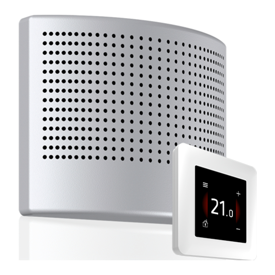
1. Components of the ECO-W
air heater
1.
Body, duct connection, heating element,
electronics section and connections for supply
voltage (230 V) and controller cabling.
2.
Grille
3.
Grille fastening screw (2 pcs)
4.
Bottom fastening screw (for the wall, 2 pcs)
2. Installation of the ECO-W air heater
1.
Drill the necessary holes in the wall for cables and fastening screws by using
the template provided with the unit (see stencil in Appendix 1).
2.
The minimum distance of the terminal device from the ceiling is 100 mm (see Figure 2.1).
Install the terminal device at a minimum height of 1.8 m.
Ensure that children cannot get their hands on the device.
3.
Detach the grille (2) from the body. Remove the two fastening screws (3) and pull the grille off the body (1).
4.
Insert the bottom section duct connector into the inlet air duct, and attach the body to the wall with screws (4)
(2 pcs, max Ø 5 mm).
5.
Connect the supply cable (MMJ) through a double-pole switch, and the control unit's data cable
to the connectors in the electronics section of the terminal device, as shown in Figure 2.2.
6.
Ensure that the connections are correct. Place the grille back onto the body and
ensure that it is properly attached with the fastening screws.
7.
Mark the power switch clearly.
Min. 10 mm
ECO-W distance from wall
© Climecon
3
2
L
N
230VAC
Figure 2.1
D- D+ V
B A
CONTROL BUS
4
L
N
CONTROL
Modbus
TERMINATION
DIP1-8:
Modbus-ID
climecon.fi
1
Figure 1.1
X1
X2
X3
Figure 2.2
1
Advertisement

Related Manuals for Climecon ECO-W


Summary of Contents for Climecon ECO-W
- Page 1 Bottom fastening screw (for the wall, 2 pcs) Figure 1.1 2. Installation of the ECO-W air heater Drill the necessary holes in the wall for cables and fastening screws by using the template provided with the unit (see stencil in Appendix 1).
- Page 2 230VAC climecon.fi Installation manual ECO-W 3. Connection CONTROL Modbus TERMINATION NOTE! Run the 230 V supply voltage to the device through a double-pole switch. Connect the supply voltage to connectors DIP1-8: D- D+ V termination Modbus-ID N and L in the electronics section of the terminal device, as shown in Figures 3.2 and 3.3.
- Page 3 Installation manual ECO-W The basic ECO connection, in which one ECO air heater The basic ECO connection, in which 2–4 ECO air heaters is controlled with a single ECO-T room control unit. are controlled with a single ECO-T room control unit.
- Page 4 Installation manual ECO-W 4. Connecting the heating of several rooms to the bus Connect the bus cables as shown in the figure. The ECO connection in which the heating of several rooms has been linked through the bus. BUS:...
- Page 5 1–4 ECO control 1–4 ECO D- D+ V D- D+ V D- D+ V air heaters air heaters Control BUS Control BUS D- D+ V D- D+ V ECO-T ECO-T Slave Slave Room 1 Room 2 Master Figure 4.3 © Climecon...
-
Page 6: Controller Installation
More detailed instructions on the system functions are provided in a separate manual. More comprehensive instructions for adjusting and scheduling room temperature can be found via the Figure 3.1 QR code or at climecon.fi/eco © Climecon... - Page 7 Installation manual ECO-W NOTE! Electrical connections may only be made by a professional electrician. Always disconnect the device from the supply voltage before maintenance! Data 230 VAC © Climecon...
- Page 8 Maintenance manual ECO-W NOTE! Maintenance may only be performed by a professional ventilation installer. Warning! The device carries a voltage of 230 V! Disconnect from the supply voltage before maintenance. © Climecon...
- Page 9 NOTE ! Must be dividable by 5 (0,5°C) Economy temperature bit 0 = Monday off/on, bit 1=Tuesday off/on, bit 2=Wednesday off/ 2013 Week program3 off/on on, bit 3=Thursday off/on, bit 4=Friday off/on, bit 5=Saturday off/on, bit 6=Sunday off/on, bit 7=program1 off/on © Climecon...
- Page 10 NOTE ! Must be dividable by 5 (0,5°C) - Economy temperature Parameter system 35001 Read only version 35002 Not used (NULL) Read only 35003 Not used (NULL) Read only 35004 Parameter file revision Read only Parameter request 35005 Read only revision © Climecon...
- Page 11 (3x) HW revision SW version major SW version minor Room temperature 0,1 °C Not used Not used Application state Application status Not used Temperature setpoint 0,1 °C Last user activity (Touch display) Not used Start unit Heating load © Climecon...
- Page 12 Number of UI slave devices alive count alive count alive count alive count alive count alive count alive count alive count alive count UI serial number 50020 low byte UI serial number 50021 high byte © Climecon...
Need help?
Do you have a question about the ECO-W and is the answer not in the manual?
Questions and answers