Advertisement
Quick Links
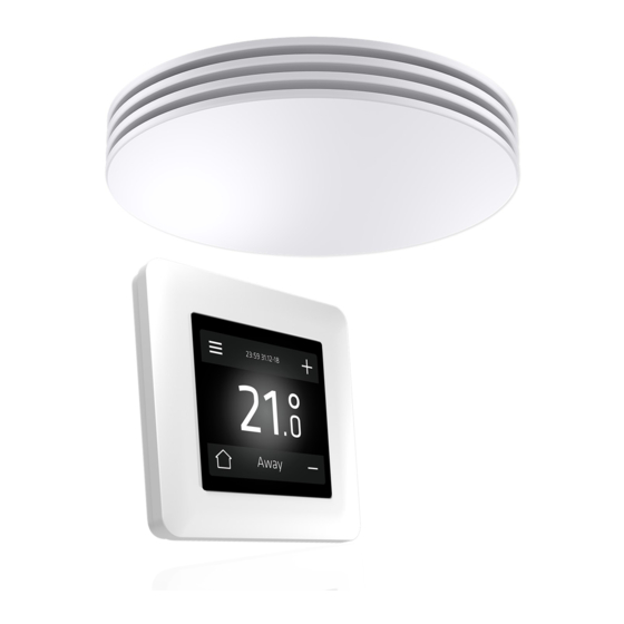
Installation manual ECO-C
Components of the ECO-C air heater
1.
Body, duct connection, heating element, electronics
section and connections for supply voltage (230 V)
and controller cabling.
2.
Grille
3.
Bottom fastening screw (3 pcs)
Installation of the ECO-C air heater
1.
Drill the necessary holes in the ceiling for cables and
fastening screws by using the stencil provided with
the unit (see stencil in Appendix 1).
2.
The minimum distance of the terminal device from the
wall is 0.5 m (see Figure 1.1). Install the terminal device
at a minimum height of 1.8 m. Ensure that children can-
not get their hands on the device.
3.
Detach the grille (2) from the body. Remove the three
fastening screws (3) and pull the grille off the body (1).
4.
Insert the bottom section duct connector into the inlet
air duct, and attach the body to the ceiling with screws
(4 pcs, max Ø 5 mm).
5.
Connect the supply cable (MMJ) through a double-pole
switch, and the control unit's bus cable (KLMA) to the
connectors in the electronics section of the terminal
device, as shown in Figures 2.1–2.3.
6.
Ensure that the connections are correct. Place the
grille back onto the body and ensure that it is properly
attached with the fastening screws.
7.
Mark the power switch clearly.
© Climecon
3
L
N
Min. 500 mm
ECO-C distance from wall
climecon.fi
1
2
Figure 1.1
Figure 1.2
1
Advertisement

Related Manuals for Climecon ECO-C


Summary of Contents for Climecon ECO-C
- Page 1 Installation manual ECO-C Components of the ECO-C air heater Body, duct connection, heating element, electronics section and connections for supply voltage (230 V) and controller cabling. Grille Bottom fastening screw (3 pcs) Installation of the ECO-C air heater Drill the necessary holes in the ceiling for cables and fastening screws by using the stencil provided with the unit (see stencil in Appendix 1).
- Page 2 Installation manual ECO-C Room unit and vent Connection 230VAC NOTE! Lead the 230 V supply voltage to the device through a double-pole switch. Connect the supply voltage D- D+ V D- D+ V to connectors N and L in the electron-...
-
Page 3: Controller Installation
To return to the main view, press the icon with the three vertical lines in the top left corner. The temperature can be adjusted with the plus and minus buttons. Figure 6 More detailed instructions on the system functions are provided in a separate manual. © Climecon... - Page 4 Installation manual ECO-C NOTE! Electrical connections may only be made by a professional electrician. Disconnect from the supply voltage before maintenance. 10 mm 10 mm © Climecon...
- Page 5 Maintenance manual ECO-C NOTE! Electrical connections may only be made by a professional electrician. Warning! The device carries a voltage of 230 V! Disconnect from the supply voltage before maintenance. 10 mm 10 mm © Climecon...
Need help?
Do you have a question about the ECO-C and is the answer not in the manual?
Questions and answers