
Related Manuals for Ross Opengear FES-6941

Summary of Contents for Ross Opengear FES-6941
- Page 1 FES-6941, FES-6942, FED-6943, FED-6944, FET-6945, and FET-6946 Fiber Ethernet Switch Transceivers User Manual...
- Page 2 Ross has become well known for the Ross Video Code of Ethics. It guides our interactions and empowers our employees. I hope you enjoy reading it below. If anything at all with your Ross experience does not live up to your expectations be sure to reach out to us at solutions@rossvideo.com.
- Page 3 Ross Video. While every precaution has been taken in the preparation of this document, Ross Video assumes no responsibility for errors or omissions. Neither is any liability assumed for damages resulting from the use of the information contained herein.
- Page 4 Operation of this equipment in a residential area is likely to cause harmful interference in which case the user will be required to correct the interference at his own expense. Notice — Changes or modifications to this equipment not expressly approved by Ross Video Ltd. could void the user’s authority to operate this equipment. Canada This Class “A”...
- Page 5 To avoid the potential release of those substances into the environment and to diminish the need for the extraction of natural resources, Ross Video encourages you to use the appropriate take-back systems. These systems will reuse or recycle most of the materials from your end-of-life equipment in an environmentally friendly and health conscious manner.
-
Page 7: Table Of Contents
Contents Introduction Overview..........................1-2 Features ..........................1-3 User Interfaces ........................1-4 DashBoard Control System ................... 1-4 Card-edge Controls....................1-4 SNMP Monitoring and Control ................1-4 Documentation Terms and Conventions................1-5 Installation Before You Begin ........................ 2-2 Static Discharge..................... 2-2 Unpacking......................2-2 Working with Fiber Optic Connectors .............. - Page 8 FED-6943 Setup FED-6943 Overview ......................5-2 FED-6943 Functional Block Diagram..............5-2 FED-6943-20A and FED-6943-20B Cabling ..............5-3 FED-6943-20A ...................... 5-3 FED-6943-20B ...................... 5-3 FED-6943-40A and FED-6943-40B Cabling ..............5-4 FED-6943-40A ...................... 5-4 FED-6943-40B ..................... 5-4 FED-6943 Technical Specifications ..................5-5 FED-6944 Setup FED-6944 Overview ......................
- Page 9 Enabling Alarms ........................ 9-12 Link Failure Alarms .................... 9-12 Power and Temperature Monitoring ..............9-12 Incompatible Rear Module Monitoring............... 9-13 DashBoard Menus Status Tabs ......................... 10-2 Signal Tab......................10-2 Hardware Tab ...................... 10-4 Product Tab ......................10-4 Port Stats Tab........................10-5 Setup Tab ...........................
- Page 10 iv • Contents Fiber Ethernet Switch Transceivers User Manual (Iss. 04)
-
Page 11: Introduction
A Word of Thanks Congratulations on choosing an openGear Fiber Ethernet Switch Transceiver. Thank you for joining the group of worldwide satisfied Ross Video customers! Should you have a question pertaining to the installation or operation of your card, please contact us at the numbers listed on the back cover of this manual. -
Page 12: Overview
Overview The Fiber Ethernet Switch Transceivers are configured in various modes depending on the number of small form-factor pluggable fiber transceivers (SFPs) installed and the rear module used. There are up to six user ports (a combination of fiber optic and RJ45 connectors) plus one GigE (SERDES) port connected to the OG3-FR series frame midplane that communicates with the switch on the Network Controller Cards. -
Page 13: Features
Features The following features are common for the Fiber Ethernet Switch Transceivers: • Compliant with IEEE 802.3 (10/100/1000BASE-T, 1000BASE-X) • Supports 10/100/1000 Base T Ethernet on RJ45 connectors • Auto negotiation for 10/100/1000 speeds, half/full duplex modes, MDI/MDIX auto-crossover • Supports two trunk groups between two devices with each trunk group having up to four ports •... -
Page 14: User Interfaces
User Interfaces The following interfaces are available for your Fiber Ethernet Switch Transceiver. DashBoard Control System DashBoard enables you to monitor and control openGear frames and cards from a computer. DashBoard communicates with the Fiber Ethernet Switch Transceiver and other cards in the openGear frame through the Network Controller Card. -
Page 15: Documentation Terms And Conventions
Documentation Terms and Conventions The following terms and conventions are used throughout this manual. Terms The following terms are used: • “Board”, and “Card” refer to openGear terminal devices within openGear frames, including all components and switches. • “CWDM” refers to models that include Coarse Wavelength Division Multiplexing lasers. •... - Page 16 1–6 • Introduction Fiber Ethernet Switch Transceivers User Manual (Iss. 04)
-
Page 17: Installation
Installation In This Chapter This chapter provides instructions for installing the rear module(s) for the Fiber Ethernet Switch Transceivers, installing the cards into the frame, cabling details, and updating the software. Caution — Every time you are required to insert a connector into a device, or mating sleeve, you must clean the connector. -
Page 18: Before You Begin
Unpack each Fiber Ethernet Switch Transceiver you received from the shipping container and ensure that all items are included. If any items are missing or damaged, contact your sales representative or Ross Video directly. Working with Fiber Optic Connectors Keep the following in mind when working with fiber optic connectors: •... -
Page 19: Physical Installation
Physical Installation This section outlines how to install a rear module and a card in an openGear frame. However, the specific rear module you need to install depends on your application. You must install the Fiber Ethernet Switch Transceiver in an OG3-FR series frame to take advantage of the internal GigE interface. -
Page 20: Installing A Card
Screw Hole Module Seating Slots Figure 2.2 Rear Module Installation in an OG3-FR Series Frame (Cards not shown) 7. Align the top hole of the rear module with the screw on the top-edge of the frame back plane. 8. Using a Phillips screwdriver and the supplied screw, fasten the rear module to the back plane of the frame. - Page 21 7. When are you ready to cable your rear module: Caution — Every time you are required to insert a connector into a device, or mating sleeve, you must clean the connector. All exposed surfaces of the ceramic ferrule must be clean. Follow your facility practices of cleaning fiber optic connectors. Connectors must always be inserted into a device or have a dust cap on.
-
Page 22: Ethernet Communications
You will require a standard network CAT-5e cable to connect the card to your facility network. (Figure 2.3) There is no need for a crossover cable as the rear modules include an Auto-MDIX ethernet PHY that will switch from straight to crossover automatically as needed. Ross Video does not supply these cables. -
Page 23: Software Upgrades
Control System. To upgrade the software on your card 1. Contact Ross Technical Support for the latest software version file. 2. In DashBoard, display the Device View of the card by double-clicking its status indicator in the Basic Tree View. - Page 24 2–8 • Installation Fiber Ethernet Switch Transceivers User Manual (Iss. 04)
-
Page 25: Fes-6941 Setup
FES-6941 Setup In This Chapter This chapter provides the cabling designations and the technical specifications for the FES-6941 Single Link Ethernet Switch Transceivers. Note that specifications are subject to change without notice. The following topics are discussed: • FES-6941 Overview •... -
Page 26: Fes-6941 Overview
FES-6941 Overview These single fiber bi-directional cards use bi-directional SFP transceivers that operate on different transmit (Tx) and receive (Rx) wavelengths over a single fiber and contain an internal WDM splitter. This gives you five links (one fiber and four RJ-45) plus the Internal Link interface. The FES-6941 series requires the 8320AR-056 Full Rear Module which includes one LC duplex fiber optic connector and four RJ-45 connectors. -
Page 27: Cabling For The Fes-6941-20A And Fes-6941-20B
Cabling for the FES-6941-20A and FES-6941-20B To calculate your fiber path link budget, refer to Table 3.2 on page 3-5 for optical budget specifications. Each of the FES-6941-20A and FES-6941-20B supports 20km cable lengths. FES-6941-20A The FES-6941-20A is used with the 8320AR-056 Full Rear Module. Each rear module occupies two slots and accommodates one card. -
Page 28: Cabling For The Fes-6941-40A And Fes-6941-40B
Cabling for the FES-6941-40A and FES-6941-40B To calculate your fiber path link budget, refer to Table 3.2 on page 3-5 for optical budget specifications. Each of the FES-6941-40A and FES-6941-40B supports 40km cable lengths. FES-6941-40A The FES-6941-40A is used with the 8320AR-056 Full Rear Module. Each rear module occupies two slots and accommodates one card. -
Page 29: Fes-6941 Technical Specifications
FES-6941 Technical Specifications This section provides the technical specifications for the FES-6941. Table 3.2 FES-6941 Technical Specifications Category Parameter Specification Number of Bi-Directional Ports FES-6941-20A, FES-6941-20B: -3dBm to -8dBm Tx Power FES-6941-40A: +2dBm to -3dBm FES-6941-40B: 0dBm to -5dBm FES-6941-20A, FES-6941-40A: 1310nm Tx Wavelength FES-6941-20B, FES-6941-40B: 1550nm Optical... - Page 30 3–6 • FES-6941 Setup Fiber Ethernet Switch Transceivers User Manual (Iss. 04)
-
Page 31: Fes-6942 Setup
FES-6942 Setup In This Chapter This chapter provides the cabling designations and the technical specifications for the FES-6942 Single Link Ethernet Fiber Transceivers. Note that specifications are subject to change without notice. The following topics are discussed: • FES-6942 Overview •... -
Page 32: Fes-6942 Overview
FES-6942 Overview The FES-6942 series provide a two fiber, and four copper (RJ45) ethernet ports. This gives you five links (one fiber and four RJ-45) plus the Internal Link interface. Each card uses a standard SFP with an FP 1310nm laser and PIN receiver. High power and CWDM transmitters are optional, as is a high sensitivity receiver. -
Page 33: Fes-6942 Functional Block Diagram
FES-6942 Functional Block Diagram This section provides a functional block diagram that outlines the workflow of the FES-6942 series regardless of the model type. Internal Link (GigE Connection to OG3-FR-CN(S)* Midplane) FIBER IN OPTICAL MODULE FIBER OUT 10/100/1000 ETHERNET SWITCH CARD CONTROL ETHERNET PORT 4... -
Page 34: Cabling For The Fes-6942-20/40/80
Cabling for the FES-6942-20/40/80 The FES-6942 is used with the 8320AR-056 Full Rear Module. Each rear module occupies two slots and accommodates one card. This rear module provides one single mode optical input, one single mode optical output, and four RJ45 Ethernet 10/100/1000 ports. If your FES-6942 is a high sensitivity transceiver, the card product number includes an “H”. -
Page 35: Cabling For The Fes-6942 Cwdm Series
Cabling for the FES-6942 CWDM Series The FES-6942 CWDM series use the same rear module as the FES-6942-20/40/80 but require a different cabling scheme. The wavelength of the optical inputs and outputs of your card is dependent on the card model. The supported wavelength is indicated in the card product number. For example, the FES-6942-27 supports 1270nm wavelengths. - Page 36 1350nm 1370nm Ethernet Port 4 Ethernet Port 4 1350nm 1370nm Ethernet Port 3 Ethernet Port 3 Ethernet Port 2 Ethernet Port 2 Ethernet Port 1 Ethernet Port 1 Figure 4.9 Cable Connections for the FES-6942-35 Figure 4.10 Cable Connections for the FES-6942-37 1430nm 1450nm Ethernet Port 4...
- Page 37 1510nm 1530nm Ethernet Port 4 Ethernet Port 4 1510nm 1530nm Ethernet Port 3 Ethernet Port 3 Ethernet Port 2 Ethernet Port 2 Ethernet Port 1 Ethernet Port 1 Figure 4.15 Cable Connections for the FES-6942-51 Figure 4.16 Cable Connections for the FES-6942-53 1550nm 1570nm Ethernet Port 4...
-
Page 38: Fes-6942 Technical Specifications
FES-6942 Technical Specifications This section provides the technical specifications for the FES-6942 series. FES-6942-20/40/80 Series This section provides the technical specifications for the FES-6942-20, FES-6942-40, and FES-6942-80. Table 4.4 FES-6942 Technical Specifications Category Parameter Specification Number of Inputs Number of Outputs FES-6942-20: 1310nm Nominal Wavelength FES-6942-40: 1310nm... -
Page 39: Fes-6942 Cwdm Series
FES-6942 CWDM Series This section provides the technical specifications for the FES-6942 CWDM series. Table 4.5 FES-6942 CWDM Series Technical Specifications Category Parameter Specification Number of Inputs Number of Outputs FES-6942-27: 1270nm FES-6942-29: 1290nm FES-6942-31: 1310nm FES-6942-33: 1330nm FES-6942-35: 1350nm FES-6942-37: 1370nm FES-6942-43: 1430nm FES-6942-45: 1450nm... - Page 40 4–10 • FES-6942 Setup Fiber Ethernet Switch Transceivers User Manual (Iss. 04)
-
Page 41: Fed-6943 Setup
FED-6943 Setup In This Chapter This chapter provides the cabling designations and the technical specifications for the FED-6943 Dual Link Ethernet Fiber Transceivers. Note that specifications are subject to change without notice. The following topics are discussed: • FED-6943 Overview •... -
Page 42: Fed-6943 Overview
FED-6943 Overview The FED-6943 series use two bi-directional SFP transceivers that operate on different transmit (Tx) and receive (Rx) wavelengths. Each SFP uses a single fiber for bi-directional signals and contain an internal WDM splitter. This gives you six links (two fiber and four RJ-45) plus the Internal Link interface. -
Page 43: Fed-6943-20A And Fed-6943-20B Cabling
FED-6943-20A and FED-6943-20B Cabling Each of the FED-6943-20A and FED-6943-20B support 20km cable lengths. FED-6943-20A The FED-6943-20A is used with the 8320AR-056 Full Rear Module. Each rear module occupies two slots and accommodates one card. This rear module provides two bi-directional optical ports and four RJ45 Ethernet 10/100/1000 ports. -
Page 44: Fed-6943-40A And Fed-6943-40B Cabling
FED-6943-40A and FED-6943-40B Cabling Each of the FED-6943-40A and FED-6943-40B supports a 40km cable length. FED-6943-40A The FED-6943-40A is used with the 8320AR-056 Full Rear Module. Each rear module occupies two slots and accommodates one card. This rear module provides two bi-directional optical ports and four RJ45 Ethernet 10/100/1000 ports. -
Page 45: Fed-6943 Technical Specifications
FED-6943 Technical Specifications This section provides the technical specifications for the FED-6943. Table 5.2 FED-6943 Technical Specifications Category Parameter Specification Number of Bi-Directional Ports FED-6943-20A, FED-6943-20B: -3dBm to -8dBm Tx Power FED-6943-40A: +2dBm to -3dBm FED-6943-40B: 0dBm to -5dBm FED-6943-20A, FED-6943-40A: 1310nm Tx Wavelength FED-6943-20B, FED-6943-40B: 1550nm FED-6943-20A, FED-6943-20B: -3dBm to -22dBm... - Page 46 5–6 • FED-6943 Setup Fiber Ethernet Switch Transceivers User Manual (Iss. 04)
-
Page 47: Fed-6944 Setup
FED-6944 Setup In This Chapter This chapter includes the technical specifications for the FED-6944 Dual Link Ethernet Fiber Transceivers. Note that specifications are subject to change without notice. The following topics are discussed: • FED-6944 Overview • Cabling for the FED-6944-20/40/80 •... -
Page 48: Fed-6944 Overview
FED-6944 Overview The FED-6944 series are a quad fiber, with three RJ-45 connection, and two port dual fiber SFPs. This gives you five links (two fiber and three RJ-45) plus the Internal Link interface. Each card uses two standard SFPs with an FP 1310nm laser and PIN receiver. High power and CWDM transmitters are optional, as is a high sensitivity receiver. -
Page 49: Fed-6944 Functional Block Diagram
FED-6944 Functional Block Diagram This section provides a functional block diagram that outlines the workflow of the FED-6944 series regardless of the model type. Internal Link (GigE Connection to OG3-FR-CN(S)* Midplane) FIBER IN A OPTICAL MODULE FIBER OUT A 10/100/1000 FIBER IN B ETHERNET OPTICAL... -
Page 50: Cabling For The Fed-6944-20/40/80
Cabling for the FED-6944-20/40/80 The FED-6944-20/40/80 is used with the 8320AR-057 Full Rear Module. Each rear module occupies two slots and accommodates one card. This rear module provides two single mode optical inputs, two single mode optical outputs, and three RJ45 Ethernet 10/100/1000 ports. The wavelength of the optical ports of your card is dependent on the card model. -
Page 51: Cabling For The Fed-6944 Cwdm Series
Cabling for the FED-6944 CWDM Series The FED-6944 CWDM series use the same rear module as the FED-6944-20/40/80, but require a different cabling scheme. The supported wavelength is indicated in the card product number. For example, the FED-6944-27 supports 1270nm wavelengths. If your FED-6944 is a high sensitivity transceiver, the card product number includes the “H”... - Page 52 1490nm 1470nm 1530nm 1510nm 1490nm 1470nm 1530nm 1510nm Ethernet Port 3 Ethernet Port 3 Ethernet Port 2 Ethernet Port 2 Ethernet Port 1 Ethernet Port 1 Figure 6.9 FED-6944-47 Figure 6.10 FED-6944-51 1570nm 1550nm 1610nm 1590nm 1570nm 1550nm 1610nm 1590nm Ethernet Port 3 Ethernet Port 3 Ethernet Port 2...
-
Page 53: Fed-6944 Technical Specifications
FED-6944 Technical Specifications This section provides the technical specifications for the FED-6944. FED-6944-20/40/80 This section provides the technical specifications for the FED-6944-20, FED-6944-40, and FED-6944-80. Table 6.4 FED-6944 Technical Specifications Category Parameter Specification Number of Inputs Number of Outputs FED-6944-20: 1310nm Nominal Wavelength FED-6944-40: 1310nm FED-6944-80: 1550nm... -
Page 54: Fed-6944 Cwdm Series
FED-6944 CWDM Series This section provides the technical specifications for the FED-6944 CWDM series. Table 6.5 FED-6944 CWDM Technical Specifications Category Parameter Specification Number of Inputs Number of Outputs FED-6944-27: 1270nm, 1290nm FED-6944-31: 1310nm, 1330nm FED-6944-35: 1350nm, 1370nm FED-6944-43: 1430nm, 1450nm Nominal Wavelength FED-6944-47: 1470nm, 1490nm FED-6944-51: 1510nm, 1530nm... -
Page 55: Fet-6945 Setup
FET-6945 Setup In This Chapter This chapter provides the cabling designations and the technical specifications for the FET-6945 Triple Link Ethernet Switch Transceivers. Note that specifications are subject to change without notice. The following topics are discussed: • FET-6945 Overview •... -
Page 56: Fet-6945 Overview
FET-6945 Overview The FET-6945 series use three bi-directional SFP transceivers that operate on different transmit (Tx) and receive (Rx) wavelengths over a single fiber and contain an internal WDM splitter. This gives you six links (three fiber and three RJ-45) plus the Internal Link interface. The FET-6945 series requires the 8320AR-057 Full Rear Module which includes four LC duplex fiber optic connectors and three RJ-45 connectors. -
Page 57: Cabling For The Fet-6945-20A And Fet-6945-20B
Cabling for the FET-6945-20A and FET-6945-20B To calculate your fiber path link budget, refer to Table 7.2 on page 7-5 for optical budget specifications. Each of the FET-6945-20A and FET-6945-20B supports 20km cable lengths. FET-6945-20A The FET-6945-20A is used with the 8320AR-057 Full Rear Module. Each rear module occupies two slots and accommodates one card. -
Page 58: Cabling For The Fet-6945-40A And Fet-6945-40B
Cabling for the FET-6945-40A and FET-6945-40B To calculate your fiber path link budget, refer to Table 7.2 on page 7-5 for optical budget specifications. Each of the FET-6945-40A and FET-6945-40B supports 40km cable lengths. FET-6945-40A The FET-6945-40A is used with the 8320AR-057 Full Rear Module. Each rear module occupies two slots and accommodates one card. -
Page 59: Fet-6945 Technical Specifications
FET-6945 Technical Specifications This section provides the technical specifications for the FET-6945. Table 7.2 FET-6945 Technical Specifications Category Parameter Specification Number of Bi-Directional Ports FET-6945-20A, FET-6945-40A: 1310nm Tx Wavelength FET-6945-20B, FET-6945-40B: 1550nm FET-6945-20A, FET-6945-20B: -3dBm to -8dBm Tx Power FET-6945-40A: +2dBm to -3dBm FET-6945-40B: 0dBm to -5dBm FET-6945-20A, FET-6945-20B: -3dBm to -22dBm Optical... - Page 60 7–6 • FET-6945 Setup Fiber Ethernet Switch Transceivers User Manual (Iss. 04)
-
Page 61: Fet-6946 Setup
FET-6946 Setup In This Chapter This chapter provides the cabling designations and technical specifications for the FET-6946 Triple Link Ethernet Switch Transceivers. Note that specifications are subject to change without notice. The following topics are discussed: • FET-6946 Overview • Cabling for the FET-6946-20A and FET-6946-20B •... -
Page 62: Fet-6946 Overview
FET-6946 Overview The FET-6946 series includes a dual fiber SFP, three copper (RJ45) ethernet ports, and two bi-directional SFP transceivers. The bi-directional SFP transceiver operates on different transmit (Tx) and receive (Rx) wavelengths over a single fiber and contain an internal WDM splitter. This gives you six links (three fiber and three RJ-45) plus the Internal Link interface. -
Page 63: Cabling For The Fet-6946-20A And Fet-6946-20B
Cabling for the FET-6946-20A and FET-6946-20B To calculate your fiber path link budget, refer to Table 8.2 on page 8-5 for optical budget specifications. Each of the FET-6946-20A and FET-6946-20B supports 20km cable lengths. FET-6946-20A The FET-6946-20A is used with the 8320AR-057 Full Rear Module. Each rear module occupies two slots and accommodates one card. -
Page 64: Cabling For The Fet-6946-40A And Fet-6946-40B
Cabling for the FET-6946-40A and FET-6946-40B To calculate your fiber path link budget, refer to Table 8.2 on page 8-5 for optical budget specifications. Each of the FET-6946-20A and FET-6946-20B supports 40km cable lengths. FET-6946-40A The FET-6946-40A is used with the 8320AR-057 Full Rear Module. Each rear module occupies two slots and accommodates one card. -
Page 65: Fet-6946 Technical Specifications
FET-6946 Technical Specifications This section provides the technical specifications for the FET-6946. Table 8.2 FET-6946 Technical Specifications Category Parameter Specification Number of Inputs Number of Outputs Number of Bi-Directional Ports Refer to the sections “Cabling for the FET-6946-20A Tx Wavelength and FET-6946-20B”... - Page 66 8–6 • FET-6946 Setup Fiber Ethernet Switch Transceivers User Manual (Iss. 04)
-
Page 67: Configuration
Configuration In This Chapter This chapter provides a general overview of the user controls and configuration options available for your Fiber Ethernet Switch Transceiver. The following topics are discussed: • Card Overview • Control and Monitoring Features • Configuring a VLAN •... -
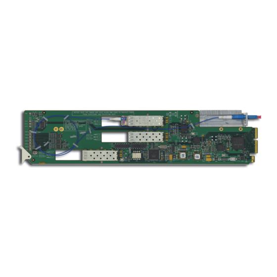
Page 68: Card Overview
Card Overview This section provides a general overview of the Fiber Ethernet Switch Transceiver card-edge components. For information on the available LEDs, refer to the section “Control and Monitoring Features” on page 9-3. Note that while an FET-6945 is described here, the card-edge components is the same regardless of the card model but the number may differ. -
Page 69: Control And Monitoring Features
Control and Monitoring Features This section provides information on the power status LED located on the card-edge and the LEDs on all rear modules for the Fiber Ethernet Switch Transceivers. Note — The number of SFP and PORT LEDs that are implemented on the card-edge is dependent on your card model. -
Page 70: Rear Module Leds
Card-edge LEDs Overview Basic LED displays and descriptions are provided in Table 9.2. Table 9.2 Card-edge LEDs Color Display and Description When lit green, this LED indicates that the card is functioning normal Green and that no anomalies have been detected. Flashing When flashing green, this LED indicates that the bootloader is currently Green... - Page 71 Rear Module LEDs Overview Basic LED descriptions are provided in Table 9.3. Table 9.3 LEDs on the Rear Modules Color Display and Description When lit green, this LED indicates a valid link is established on Green the specified RJ45 port. When flashing green, this LED indicates communication activity ETHERNET Flashing Green...
-
Page 72: Configuring A Vlan
Configuring a VLAN A virtual local area network (VLAN) is a logical grouping of workstations, servers, and network devices so that they appear to be on the same LAN whether they are part of a larger local LAN or geographically dispersed. A VLAN allows a network of computers and users to communicate in a simulated environment as if they exist in a single LAN and are sharing a single broadcast and multicast domain. - Page 73 VLAN 1 RJ45 #1 FIBER 1 VLAN 2 RJ45 #2 FIBER 2 RJ45 #3 FIBER 3 INTERNAL LINK FET-6945 Figure 9.7 Example of Multiple VLAN Setup using a Single FET-6945 For More Information on... • the ports for your card, refer to the applicable chapter in this manual. To enable a VLAN setup 1.
- Page 74 • Select the applicable VLAN # check box for each port you wish to include. The box displays a check-mark. Note that the number of ports depends on the card model. Note — A minimum of two ports must be assigned to a VLAN in order to establish communications.
-
Page 75: Enabling Trunking
Enabling Trunking Trunking, also known as link aggregation, is the use of two or more links between nodes (switches and/or servers) in parallel to increase the bandwidth. A side benefit is that a failure of a link will cause the traffic to be redistributed among the remaining links, though at reduced overall capacity. -
Page 76: Configuring A Trunking Group
Troubleshooting a Loop When a loop is created, the Fiber Ethernet Switch Transceiver may automatically detect the loop and disable the appropriate ports. When this occurs, the LEDs on the rear module and the card-edge flash in unison for the affected ports. Note that the network may be able to avoid the loop if it has spanning tree capability. - Page 77 To configure a Trunk Group 1. From the Device View, select the Setup tab. FET-6945 — Configuring a Trunk Group 2. Select the Enable Trunking check box. 3. In the Port Enables area, select the required check boxes to activate the specified RJ45, and Fiber ports on your card.
-
Page 78: Enabling Alarms
Enabling Alarms You can configure the Fiber Ethernet Switch Transceivers to report when one or more of the following error conditions occur: • A link fails on the card switch • An incompatible rear module is installed with the card •... -
Page 79: Incompatible Rear Module Monitoring
4. To monitor the optical receiver power consumption of the card, select the applicable RX Power High and Rx Power Low check boxes to enable the card to report when the receiver power is not within the recommended range for the SFPs. To enable temperature monitoring 1. - Page 80 9–14 • Configuration Fiber Ethernet Switch Transceivers User Manual (Iss. 04)
-
Page 81: Dashboard Menus
DashBoard Menus In This Chapter This chapter briefly summarizes the menus, items, and parameters available from DashBoard for the Fiber Ethernet Switch Transceiver. Note that default values are indicated with an asterisk (*). Note — The Fiber Ethernet Switch Transceivers do not support DataSafe. The following topics are discussed: •... -
Page 82: Status Tabs
Status Tabs This section summarizes the read-only information displayed in the Status tabs. The fields in the Status tabs can vary in severity from green (valid), yellow (caution), to red (alarm). DashBoard reports the most severe alarm for a single field. Alarm colors are noted within the tables as text set in brackets next to the menu parameter name. - Page 83 Table 10.1 Signal Tab Items Tab Title Item Parameters Description # Mbps Indicates the duplex and speed of the specified port # Gbps Fiber # Rate The link has failed No Link The link is invalid # Mbps Indicates the duplex and speed of the Ports GigE connection to the OG3-FR # Gbps...
-
Page 84: Hardware Tab
Table 10.3 Product Tab Items Tab Title Item Parameters Description Product Displays the card name Supplier Ross Video Ltd. Board Rev Indicates the board revision Board S/N ###### Indicates the card serial number Product Indicates the Rear Module installed Indicates the rear module is either an... -
Page 85: Port Stats Tab
Port Stats Tab Table 10.4 summarizes the read-only information displayed in the Port Stats tab. Note — The number of RJ45 and Fiber Link Status fields in the Port Stats tab is dependent on your card model. Table 10.4 Port Stats Tab Items Menu Title Item Parameters... -
Page 86: Setup Tab
Setup Tab Table 10.5 summarizes the Setup options available in DashBoard. Note that the number of configurable Port fields in the Setup tab is dependent on your card model. Important — Contact your IT Department before connecting to your facility network to ensure that there are no conflicts or the possibility of creating a network loop. -
Page 87: Alarm Enable Tab
Alarm Enable Tab Table 10.6 summarizes the Alarm setup options available in DashBoard. Note — The number of sub-tabs, RJ45 Link check boxes, and Fiber Link check boxes in the Alarm Enable tab is dependent on your card model. Table 10.6 Alarm Enable Menu Items Menu Title Item Parameters... - Page 88 Table 10.6 Alarm Enable Menu Items Menu Title Item Parameters Description Enables the corresponding Optical Tx Power field in the Signal tab to report Selected* when the optical receiver power of the TX Power Low Optical Module is outside the SFP recommended range Cleared Disables this alarm for the specified port...
-
Page 89: Service Information
Service Information In This Chapter This chapter contains the following sections: • Troubleshooting Checklist • Warranty and Repair Policy Fiber Ethernet Switch Transceivers User Manual (Iss. 04) Service Information • 11–1... -
Page 90: Troubleshooting Checklist
Bootload Button In the unlikely event of a complete card failure, you may be instructed by a Ross Technical Support specialist to perform a complete software reload on the card. -
Page 91: Warranty And Repair Policy
In the event that your Fiber Ethernet Switch Transceiver proves to be defective in any way during this warranty period, Ross Video Limited reserves the right to repair or replace this piece of equipment with a unit of equal or superior performance characteristics. - Page 92 Contact Us Contact our friendly and professional support representatives for the following: • Name and address of your local dealer • Product information and pricing • Technical support • Upcoming trade show information Telephone: +1 613 • 652 • 4886 Technical After Hours Emergency: +1 613 •...
Need help?
Do you have a question about the Opengear FES-6941 and is the answer not in the manual?
Questions and answers