
Related Manuals for VIPA IO Smart Series

Summary of Contents for VIPA IO Smart Series
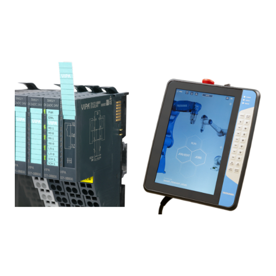
- Page 1 VIPA CONTROLS VIPA SLIO Remote I/O The remote I/O system, Yaskawa Smart Pendant & Yaskawa Robot Controller Tutorial...
-
Page 2: Table Of Contents
VIPA I/O Expansion Kit for Smart Series ..................2 Kit Contents ..........................3 What’s Not Included in the Kit ....................3 Setup for VIPA I/O Expansion Kit & Robot Controller ..............4 Mount VIPA Kit .......................... 4 Power VIPA Kit ......................... 5 Network Configuration ...................... -
Page 3: Vipa I/O Expansion Kit For Smart Series
VIPA IO Smart Series VIPA I/O Expansion Kit for Smart Series This document describes how to configure and test a VIPA EtherNet/IP Coupler + Configurable SLIO Modules with the YRC1000 and YRC1000micro Controllers (collectively referred to as YRC Controller in this document). These instructions are valid for all types of SLIO modules;... -
Page 4: Kit Contents
Kit Contents Kit Contents Three VIPA I/O expansion kits are available for Yaskawa robot controllers: 16 IN, 16 OUT Digital I/O: Part # 099-1IP20 Includes: 1x SLIO 053-1IP01 / EtherNet/IP Interface Module SLIO 007-0AA00 / Power Module (embedded with Interface Module) 2x SLIO 021-1BF00 / 8 Digital Inputs PNP 2x SLIO 022-1BF00 / 8 Digital Outputs PNP, 0.5A... -
Page 5: Setup For Vipa I/O Expansion Kit & Robot Controller
VIPA IO Smart Series Setup for VIPA I/O Expansion Kit & Robot Controller These instructions will be used to configure a VIPA I/O Expansion Kit on a Smart Series system. Mount VIPA Kit 1. To mount/demount the EtherNet/IP coupler, use the locking levers on top of the bus coupler. -
Page 6: Power Vipa Kit
Setup for VIPA I/O Expansion Kit & Robot Controller Power VIPA Kit Terminals with spring clamp technology are used for wiring SLIO modules. This vibration proof technology allows for quick and easy connection of your signal and supply lines. 1. Insert a screwdriver at an angle into the square opening as shown above. -
Page 7: Network Configuration
The VIPA expansion kit should be connected to the YRC controller through one of the Ethernet ports on 053-1IP01. A PC can also be connected to configure the VIPA kit using its web server. See network configurations for both the YRC1000micro and YRC1000 controllers below: Configure VIPA IP Address The IP address of the EtherNet/IP bus coupler is determined by physical “address switches”. - Page 8 Information corresponding to the tab selected in 2) If the VIPA kit needs to be configured on a network outside of 192.168.1.x, this can be changed from the IP tab of the web server. For example, the following figure shows changing the IP...
- Page 9 Note: after editing the IP address, physical address switches 1 to 7 must be reset to “0” to avoid overwriting the IP address entered in the web server. Ping both the VIPA kit and the YRC Controller from a PC to verify communication has been established using the custom IP configuration.
-
Page 10: Configure Yaskawa Robot Controller
This section provides the steps require to configure the YRC Controller for successful communication with a VIPA Smart Series I/O kit. VIPA 099-1IP20 is used as an example in this guide - similar steps should be followed for other VIPA kits. - Page 11 Selecting a device will display its details on the bottom panel. 3. Create a “New Allocation” for VIPA with data from web server 1) Press {+ New Allocation} at the top of the I/O Configuration Screen. Select “EtherNet/IP Scanner”...
- Page 12 In Step #3, the Starting Group #’s were automatically set to the first available range of bytes in each respective table. If a custom location is desired, the Input Table and Output Table tabs can be used to edit where I/O dedicated for the VIPA kit lands on the controller.
- Page 13 Yaskawa recommends placing the allocation for the VIPA kit near the EtherNet/IP Status byte. In the example shown above, the EtherNet Status byte is located at Group 10 and the VIPA allocation begins in Group 11. Additionally, “Starting Group #” for Inputs and Outputs should match (both set to 11 above).
- Page 14 Setup for VIPA I/O Expansion Kit & Robot Controller If “Size (bytes)” or “Starting Group #” are modified, Smart Pendant will check whether the edit(s) conflict with any other devices. As shown below, a message will appear if conflict(s) exist, preventing the user from pressing {Save} until they are resolved.
- Page 15 5. Reboot robot controller to activate new configuration In Steps #3 and #4, new data was entered/edited for the VIPA I/O kit and saved by the user. When the edited data is saved, a message will appear alerting the user to reboot the controller to activate the new devices configuration.
- Page 16 Setup for VIPA I/O Expansion Kit & Robot Controller Additionally, the EtherNet/IP Status byte on Smart Pendant can be used to diagnose communication. Navigate to {Menu} > {I/O & Variables} > {I/O} screen. Use the {Settings} button on the I/O screen to ensure the EtherNet/IP Status byte is visible.
-
Page 17: Vipa I/O Expansion Kit Details
VIPA I/O Expansion Kit Details VIPA IO Smart Series VIPA I/O Expansion Kit Details Data Layout The data in the EtherNet/IP communications packet will automatically populate according to the physical configuration of the devices in the rack. For example, see the example shown below: First, a 3-byte buffer is present before the start of Input data (green). - Page 18 VIPA I/O Expansion Kit Details The web server can also be used to easily identify where the data for a specific device is located. For example, below shows the data for an Input Module. The “Offset” value is the location from the start of the Input Data. For example, if the data is mapped to Input Group #5 as shown in this example, then this data will be located at Input Group #8 (3+5) and will take 1 byte of data.
-
Page 19: Using Digital I/O Modules
Using Digital I/O Modules VIPA IO Smart Series Using Digital I/O Modules The following sections provide detail on the wiring, Smart Pendant setup, and Smart Pendant programming methods for VIPA Digital I/O modules. Wiring Detail for PNP Digital Inputs (021-1BF00) -
Page 20: Wiring Detail For Pnp Digital Outputs (022-1Bf00)
Using Digital I/O Modules Wiring Detail for PNP Digital Outputs (022-1BF00) -
Page 21: Digital I/O On Smart Pendant
In Teach Mode, Digital Outputs can be toggled. Activate the “Enable toggle” checkbox in Management security level. Output bits can be selected on right panel to turn ON/OFF. Green lights on VIPA SLIO module will indicate whether the Output is ON / OFF. Programming Smart Pendant provides several I/O related INFORM “Commands”... -
Page 22: Using Analog I/O Modules
Using Analog I/O Modules Using Analog I/O Modules The following sections provide detail on the wiring and Smart Pendant programming methods for VIPA Analog I/O modules. Wiring Detail for Analog Inputs (Current: 031-1BF60, Voltage: 031-1BF74) -
Page 23: Wiring Detail For Analog Outputs (Current: 032-1Bd40, Voltage: 032-1Bd70)
Using Analog I/O Modules VIPA IO Smart Series Wiring Detail for Analog Outputs (Current: 032-1BD40, Voltage: 032-1BD70) -
Page 24: Analog I/O On Smart Pendant
Using Analog I/O Modules Analog I/O on Smart Pendant VIPA Analog I/O modules have a variety of configurations as shown below. The device used in this example uses the 12-bit configuration from this table. As discussed earlier, the first Analog Output is mapped to Output Group #6-7 for this example. - Page 25 Using Analog I/O Modules VIPA IO Smart Series Example Smart Pendant Job for setting Analog Output(s) /JOB //NAME SETVOLTAGE //POS ///NPOS 0,0,0,0,0,0 //ARGINFO ///ARGTYPE B,,,,,,, ///COMMENT Voltage //INST ///DATE 2019/10/31 00:21 ///ATTR SC,RW ///GROUP1 RB1 ///LVARS 5,0,10,10,0,0,0,0 GETARG LR000 IARG#(1)
-
Page 26: Replacement Of Ethernet/Ip 053-1Ip00 By 053-1Ip01
Using Analog I/O Modules Replacement of EtherNet/IP 053-1IP00 by 053-1IP01 If replacing EtherNet/IP coupler 053-1IP00 (previous model) with 053-1IP01, adjustments to the Input and Output assemblies are required. Following the setup instructions in this guide will successfully perform these adjustments. Reference the figure below for further detail on the differences between the two couplers, required instance IDs, and the structure of the 1-byte Input header. -
Page 27: Vipa Slio Product Line
VIPA SLIO Product Line VIPA IO Smart Series VIPA SLIO Product Line Use the following links to find more details on available SLIO products & configurations: >> SLIO At-A-Glance: https://vipausa.com/slio-at-a-glance/ • SLIO Overview: https://vipausa.com/slio/ CPUs: https://vipausa.com/cpu/ • Clamp Modules: https://vipausa.com/power-terminal-modules/ •...
Need help?
Do you have a question about the IO Smart Series and is the answer not in the manual?
Questions and answers