Table of Contents
Advertisement
Quick Links
Manufacturer:
FLUXANA GmbH & Co.KG
Borschelstr. 3
47551 Bedburg-Hau - Germany
Tel.
+49 2821 / 48011-10
Fax. +49 2821 / 48011-99
info@fluxana.de
www.fluxana.com
FXBA‐0096‐10
USER MANUAL
VITRIOX GAS
Gas‐Powered Fusion Machine
Service and Support:
FLUXANA GmbH & Co.KG
Borschelstr. 3
47551 Bedburg-Hau - Germany
Tel.
+49 2821 / 48011-10
Fax. +49 2821 / 48011-99
service@fluxana.de
www.fluxana.com
1 / 18
Advertisement
Table of Contents

Subscribe to Our Youtube Channel
Related Manuals for FLUXANA VITRIOX GAS Series

Summary of Contents for FLUXANA VITRIOX GAS Series
- Page 1 Gas‐Powered Fusion Machine Manufacturer: Service and Support: FLUXANA GmbH & Co.KG FLUXANA GmbH & Co.KG Borschelstr. 3 Borschelstr. 3 47551 Bedburg-Hau - Germany 47551 Bedburg-Hau - Germany Tel. +49 2821 / 48011-10 Tel. +49 2821 / 48011-10 Fax.
-
Page 2: Table Of Contents
FXBA‐0096‐10 2 / 18 Content 1.0 Technical Data 2.0 Instrument views 2.1 Rear view 2.2 Front view 2.3 Top view (4 Stations) 3.0 Unpacking and Setting Up 4.0 General Description of Function 5.0 Description: Touch‐Display 5.1 ... -
Page 3: Technical Data
FXBA‐0096‐10 3 / 18 1.0 Technical Data Instrument Type VITRIOX GAS 2XRF VITRIOX GAS 4XRF VITRIOX GAS 6XRF Number of fusion 2 4 6 stations Supply voltage 115 or 240 VAC / 50/60 Hz 115 or 240 VAC / 50/60 Hz 115 or 240 VAC / 50/60 Hz Power consumption 150 W 200 W 200 W Protection class IP2 IP2 IP2 Recommended air 4 bar 4 bar 4 bar pressure Maximum air pressure 8 bar 8 bar 8 bar Recommended gas 250 mbar ... -
Page 4: Instrument Views
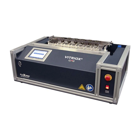
FXBA‐0096‐10 4 / 18 2.0 Instrument views 2.1 Rear view 1 – Gas connection (hose fitting 9 mm, outer diameter) 2 – Air pressure gauge 3 –Air connection (hose fitting 9 mm, outer diameter) 4 – Oxygen connection (hose fitting 6 mm, outer diameter) 5 – Power connection 6 – Fuse (4A) 7‐ Network connection ... - Page 5 FXBA‐0096‐10 5 / 18 2.2 Front view 1 = Touch display 2 = Emergency stop button 3 = Machine power switch – Main switch, “Power” ...
- Page 6 FXBA‐0096‐10 6 / 18 2.3 Top view (4 Stations) 1. Crucible burner 2. Mold burner 3. Crucible 4. Mould 5. Ceramic bar for mould 6. Ceramic stop for mould ...
-
Page 7: Unpacking And Setting Up
FXBA‐0096‐10 7 / 18 3.0 Unpacking and Setting Up Examine the transport box for external damage. If there is visual damage write a report and have it confirmed by the carrier. Open the transport box and remove the transport locks. Carefully lift the machine out of the box and place it in the operating position. Warning! Do not raise the machine by lifting on the mobile carriage (agitating mechanism)! Connect the power cable (“Power”) 115 or 240 VAC / 50/60 Hz. Connect the compressed air to the “Air” hose fitting with a hose clamp. Inner diameter of the hose for compressed air is 9 mm. Air pressure: min. 4 bar, max. 8 bar Connect the oxygen to the “Oxygen” hose fitting with a hose clamp. Inner diameter of the hose for oxygen is 6 mm. Oxygen pressure: min. 2 bar, max 2 bar Connect the gas to the “Gas” hose fitting with a hose clamp. Inner diameter of the hose for gas is 9 mm. Gas pressure: min. 200 mbar, max. 500 mbar The operating position must be selected so that the ventilation slits on both sides of the device are not obstructed. We highly recommend to use a fume hood. The use of an external gas detector at the site of operation is strongly advised. ... -
Page 8: General Description Of Function
Target time (30sec) and Actual time. The ignition continues until the thermocouples are hot, for a maximum of 30 sec. If the thermocouples have not been heated enough by the pilot flames within this time, the device can be started again. The pilot flames will then start the crucible burners. After the start all burner stations can be individually or simultaneously switched on/off during the fusion process. This is not possible with devices with optional mould sensors. Here the stations must be selected before the start. The agitation mechanism can be also switched on in the prefusion process. From Mainfusion 1 on, the agitating is switched on as default. Agitation times and rest times can be set separately. The mold burners are automatically switched on during the Mainfusion 2. They are ignited by the pilot burner. After pouring the melt out of the crucible into the moulds, they are cooled first with low pressure air (cooling 1) and then cooled in the next two steps with increasing pressure. The flow of the cooling air is set in the display. The target times in all application steps (preheating, prefusion, agitating, main fusion 1 & 2, pouring and cooling) can be set individually ‐ 10 different applications can be stored. We only recommend changing the times of the application steps (preheating, pre‐fusion, main fusion 1 and cooling 3). The times for main fusion 2 and cooling 1 & 2 have proven themselves in our application laboratory for years. Crucible burner, mold burners, agitation, cooling and pilot burner switch off automatically at the end of the application. After the last step: cooling 3, the machine returns to the base screen. Program End is shown in the display. Acknowledge this message by pressing. The VITRIOX GAS devices are equipped with a gas sensor that blocks the main gas and oxygen supplies and stops the running application immediately if a gas leak in/or near the device is detected. The display shows the message: Gas leakage. Be sure to contact the Fluxana Service (see page 1) before restarting. ... -
Page 9: Description: Touch-Display
FXBA‐0096‐10 9 / 18 5.0 Description: Touch‐Display The base screen is displayed after pressing the “Power” button: 5.1 Function Keys: Appl = Application can be selected Station = stations can be switched on and off Modify = Applications can be changed Load = selected application is read Start = Application is started Settings = Settings for mould, gas and feed sensor ... - Page 10 FXBA‐0096‐10 10 / 18 5.1.1 Function key Appl Application: individual stored applications can be selected via a numeric keypad. 2 applications (Appl.0 & Appl.1) are preinstalled as standard. The 8 following memory slots are at your disposal. Different times and temperatures in the individual application steps characterize different materials and methods. 5.1.2 Function key Load Application No. 0 is automatically loaded when the device is switched on. After selecting the application, type application number 0 ‐ 9 and confirm with ENTER. read application with Load. 5.1.3 Function key Modify With Modify the respective application steps (left side) can be called. In the selected application step, the time can be checked or changed. Another possibility is to check or change the flow rates for gas, oxygen and air depending on the number of stations (consumers). With Agitat, the agitating functions, as well as the agitating speed and times are checked or changed. The pouring time is set under Pouring. ...
- Page 11 FXBA‐0096‐10 11 / 18 To save changed entries, first you need to log in as admin. To do this, press Modify from the base screen, then press User, in the new window select Admin, enter the password and confirm with Enter. Press Save to store all new entries (these are retained even after the device has been switched off). Exit this page with Menu. 5.1.4 Function key Settings: Optional mould sensor: enable/disable function Gas sensor: unlock the Gas leakage message Feed sensor: enable/disable function ...
-
Page 12: Copying An Application
FXBA‐0096‐10 12 / 18 6.0 Copying an Application This can be used to shorten the creation of a new application, or to create a backup of an existing application on a free memory slot. 1. Load a stored application, e.g. Appl. 1 ‐ (see function key Load). 2. Enter the new application number in Appl (do not press Load). 3. Press Modify, change the desired values. 4. Press Save. 7.0 Changing the fusion times during the running application The device allows to change the times in the application steps preheating, prefusion, main fusion 1, main fusion 2, pouring and cooling individually during the running application. This enables the user to observe the melting process and intervene depending on the progress. In the Mainfusion 2, the time should ALWAYS be 240 sec, since the mould burners are set to optimum temperature before pouring. Example for shortening the Mainfusion time: The device is currently in the Mainfusion 1, Target = 240 sec. After inspection, the main fusion should end after 180 seconds: Press Target time 240 and enter the new time, e.g., 180. Confirm with ENTER. If the actual time is ≤ Target time, this application step stops and the next step begins. Increasing the Mainfusion time works in the same way. According to the examples above, all displayed times in the different application steps can be changed during the process. ... -
Page 13: Application With Low Temperature
FXBA‐0096‐10 13 / 18 8.0 Application with low temperature The VITRIOX GAS device not only allows the setting of different time sequences in the individual applications, but also different temperature profiles. These two parameters enable a time‐optimized and/or material‐specific adjustment of the fusion process. The device thus allows a largely individual adaptation to different requirements. In the preheating step, e.g. a low temperature can be set to e.g. to dry the crucible contents, or to perform an oxidation. Thereafter (from prefusion on), the normal melting temperature is used. 9.0 Using the platinum ware Place the platinum crucible with sample into the receptacle holes in the crucible holder. Hang the crucibles on the notches and push the crucible to the left until it is in the correct position. Place the moulds onto the ceramic bars and push them up to the ceramic stop. ... -
Page 14: Timing Of The Preinstalled Application 0
FXBA‐0096‐10 14 / 18 10.0 Timing of the preinstalled Applications 0 & 1: Application 0: „Preheating“ 180 seconds „Prefusion“ 240 seconds „Mainfusion 1“ 120 seconds „Mainfusion 2“ 240 seconds „Agitating off“ 10 seconds „Agitating on“ 10 seconds „Pouring“ 7 seconds „Cooling“complete 360 seconds (60/240/60) Application 1: „Preheating“ ... -
Page 15: Service, Replacing Consumables
FXBA‐0096‐10 15 / 18 11.0 Service, Replacing Consumables 11.1 Replacing a burner Turn off the device. Pull out the power plug and let it cool down, if necessary. Loosen the cap nut with the special wrench delivered with the device. The burner can then be removed. The new burner is installed in the reverse order. 11.2 Changing the belt (PD‐SKF0005c) of the agitating device (eccentric). Pull the eccentric upwards out of the motor plate. Put round belt on the motor plate and put the eccentric back in the holes of the motor plate. Now place the round belt over the grooves of the drive pulleys. Figure: Agitation mechanism 11.3 Replacing the toothed belt (PD‐SKF0006) of the agitating device (eccentric) Release screws for crucible holder (1) from eccentric, then pull eccentric from above out of the motor plate. Loose hex screws (2), and now push the right shaft with gear inward until the toothed belt moves freely Look over the top edge, both shafts should be in the same position ... - Page 16 FXBA‐0096‐10 16 / 18 Upper edge Position of the shafts When the positions are the same, push the right shaft outward again and try to find out if the toothed belt is in the right position. If not, adjust until everything fits. Now tighten the screws slightly and insert the eccentric into the motor plate. If the shafts rotate easily in the bearings, tighten the screws. Now mount the carriage back to the eccentric. We recommend an annual service for the device. ...
-
Page 17: Warranty Terms For Vitriox Gas Series
FXBA‐0096‐10 17 / 18 12.0 Warranty terms for VITRIOX GAS series Parts and equipment manufactured by the producer are warranted from defect in material and workmanship for a period of 12 months from the date of installation but no longer than 15 months from the date of delivery (depending on what occurs first). Other parts or equipment are covered to the extent of warranty provided by the original manufacturer. The producer makes no other warranty with respect to merchantability, fitness for purpose, or otherwise. Consumables and items of similar nature are not covered by this warranty. The producer's sole obligation under this warranty shall be to repair or replace any part or parts which, to our satisfaction, prove to be defective upon return prepaid to the producer. This obligation does not cover any failure due to accident, abuse, neglect, or use in disregard of instructions furnished by the producer. In no event shall damages for defective goods exceed the purchase price of the goods, and the producer shall not be liable for incidental or consequential damages whatsoever. All claims in regard to the parts or equipment must be made in writing within 10 days after the purchaser learns of the facts upon which the claim is based. Written authorization must be obtained from the producer prior to returning any part or parts. This warranty is voided by failure to comply with these notice requirements. The warranty on the machine remains valid only when genuine replacement parts are employed. Only technically qualified staff who have fully read and understood these instructions should operate this machine. The operator should follow all of the warnings and cautions set forth in this manual and should follow the applicable safety procedures. Service and repairs should be carried out only by the manufacturer or by its appointed and trained representatives. 13.0 EC Declaration of Conformity ... -
Page 18: Ec Declaration Of Conformity
Instrument Type: Attach type label here has been developed, constructed and manufactured in satisfaction of the above named directives by ® FLUXANA GmbH & Co.KG Borschelstr. 3 47551 Bedburg‐Hau This declaration relates exclusively to the machinery in the state in which was placed on the market and excludes components which are added and/or operations carried out subsequently by the end user. The following harmonized standard applies: DIN EN ISO 12100:2011‐03 Person authorized to compile the technical file is: Mr. Volker Gossens, address as above. ...
Need help?
Do you have a question about the VITRIOX GAS Series and is the answer not in the manual?
Questions and answers