Table of Contents
Advertisement
User manual and technical description
Manufacturer:
FLUXANA® GmbH & Co.KG
Borschelstr. 3
D‐47551 Bedburg‐Hau
Tel. +49 (0)2821 / 48011‐10
Fax. +49 (0)2821 / 48011‐99
E‐mail: info@fluxana.de
Homepage: http://www.fluxana.com
FXBA‐0072‐17
VITRIOX® ELECTRIC
Service and support:
FLUXANA® GmbH & Co.KG
Borschelstr. 3
D‐47551 Bedburg‐Hau
Tel. +49 (0)2821 / 48011‐10
Fax. +49 (0)2821 / 48011‐99
E‐mail: info@fluxana.de
Homepage: http://www.fluxana.com
1 / 42
Advertisement
Table of Contents

Subscribe to Our Youtube Channel
Related Manuals for FLUXANA VITRIOX ELECTRIC

Summary of Contents for FLUXANA VITRIOX ELECTRIC
- Page 1 FXBA‐0072‐17 1 / 42 VITRIOX® ELECTRIC User manual and technical description Manufacturer: Service and support: FLUXANA® GmbH & Co.KG FLUXANA® GmbH & Co.KG Borschelstr. 3 Borschelstr. 3 D‐47551 Bedburg‐Hau D‐47551 Bedburg‐Hau Tel. +49 (0)2821 / 48011‐10 Tel. +49 (0)2821 / 48011‐10 Fax. +49 (0)2821 / 48011‐99 Fax. +49 (0)2821 / 48011‐99 E‐mail: info@fluxana.de E‐mail: info@fluxana.de Homepage: http://www.fluxana.com Homepage: http://www.fluxana.com ...
-
Page 2: Table Of Contents
FXBA‐0072‐17 2 / 42 Table of Contents 1. Overview 1.1 Product Description 1.2 Overview of the system 1.3 Technical data 1.4 Models 1.5 Protective Housing 1.6 Hood with fan 2. Warranty and Liability 3. Safety 3.1 Intended Use 3.2 Requirements of the system operator 3.3 Requirements of the operating personal 3.4 Protective clothing 3.5 Basic measures for normal operation 3.6 Behavior in case of emergency 3.7 Basic measures for upkeep and maintenance ... -
Page 3: Overview
FXBA‐0072‐17 3 / 42 1. Overview 1.1 Product Description The VITRIOX® ELECTRIC is a fusion instrument for sample preparation for X‐ray fluorescence analysis. The fusion chamber is heated by systematically arranged heating elements that are isolated from the fusion chamber. In this way, it is possible to achieve ideal heating of the fusion chamber. Temperature determination is conducted with a special thermoelement. The fusion chamber can be heated to up to ... - Page 4 FXBA‐0072‐17 4 / 42 Overview of the system 11 Front side of the oven: 1. Fusion chamber 2. Display (Touchscreen) 3. Emergency Stop button 4. Power switch 5. USB‐Connection 6. Bottom holder (Reservoir) 7. Bottom insolation 8. Rotation unit 9. Setup station 10. Extra cooling station 11. Mirror Rear side of the oven: 1. Power supply 2.
-
Page 5: Technical Data
FXBA‐0072‐17 5 / 42 1.3 Technical Data 4 Stations / 6 Stations / Technical Data 1 Station 2 Stations 2 Stations with COO 4 Stations with COO 230 V / 208 V 230 V / 208 V 230 V / 208 V 230 V / 208 V Voltage: 50‐60 Hz 50‐60 Hz 50‐60 Hz 50‐60 Hz Power: 3000 W 3000 W 3000 W 3000 W 1~ AC / 16 A 1~ AC / 16 A 1~ AC / 16 A 1~ AC / 16 A 2~ AC / 16 A 2~ AC / 16 A 2~ AC / 16 A 2~ AC / 16 A Power supply: ... -
Page 6: Models
FXBA‐0072‐17 6 / 42 1.4 Models The following drawings are examples but contain the actual dimensions. VITRIOX® ‐ 1 Station: ... - Page 7 FXBA‐0072‐17 7 / 42 VITRIOX® ‐ 2 Stations: ...
- Page 8 FXBA‐0072‐17 8 / 42 VITRIOX® ‐ 4 Stations, continuous operation option (COO): ...
- Page 9 FXBA‐0072‐17 9 / 42 VITRIOX® ‐ 4 Stations: ...
- Page 10 FXBA‐0072‐17 10 / 42 VITRIOX® ‐ 6 Stations: ...
- Page 11 FXBA‐0072‐17 11 / 42 ...
-
Page 12: Hood With Fan
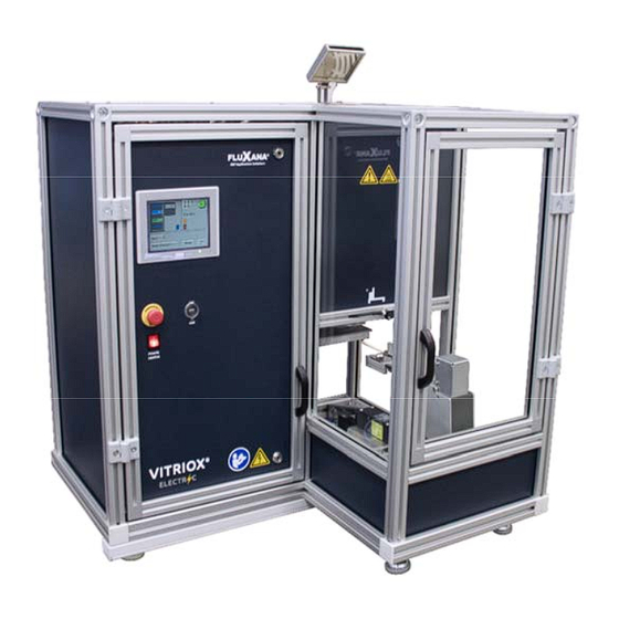
FXBA‐0072‐17 12 / 42 1.5 Protective Housing Fig. 1: Protective housing made of aluminum system profiles and safety glass (heat‐resistant glass in the hot area) 1.6 Hood with fan Fig. 2.: Example installation of a hood with built‐in fan above the Electrical Fusion Machine. ... -
Page 13: Warranty And Liability
FXBA‐0072‐17 13 / 42 Fig. 2: Name plate 2 Warranty and Liability § The FLUXANA® warranty conditions or individual contract‐regulated warranties apply with regard to warranty and liability. The following also applies: Warranty and liability claims for personal and property damage are excluded if they are due to one or more of the following causes: • All persons involved with operation, installation, maintenance or repair of the system must have read and understood the operating instructions. We shall assume no liability for damage or operational interruptions resulting from failure to observe the operating instructions. • usage not according to the intended purpose of the system, • incorrect setup, installation, operation or maintenance of the system, • operation of the system with defective safety devices or incorrectly installed or non‐functional safety or protection equipment, • non‐observation of the instructions in the operating instruction concerning transport, storage, setup, installation, operation, maintenance or upgrading of the system, • unauthorized structural modifications to the system, • unauthorized changes to the operating parameters, ... -
Page 14: Safety
FXBA‐0072‐17 14 / 42 3 Safety 3.1 Intended Use Only materials for which the properties and fusion temperatures are known may be used with the electrical fusion machine. The safety data sheets for the respective materials should be consulted in case of doubt. The processing of other products and the handling of hazardous materials as well as all changes to the system equipment require the written consent from the FLUXANA® GmbH & Co. KG. Protective equipment may not be removed, circumvented or deactivated. It must be known if the material used could attack or destroy parts of the oven, such as the insulation or the heating elements. The oven shall be deemed not used as intended and any claim whatsoever against the FLUXANA® GmbH & Co. KG shall be void if the installation instructions and safety requirements are not met. Operation with power sources, products, equipment, aids, etc., that are subject to the Hazardous Substances Act or in any way cause adverse impacts on the health of the operating personnel is not allowed. ‐ This oven has been designed for commercial use. The oven may not be used for the heating of food for people or animals, wood, grain, etc. ‐ The oven must not be used for heating of the workspace. ‐ Do not use the oven to melt ice or other similar substances. ‐ Do not use the oven as a clothes dryer. Note: The safety instructions in the individual chapters shall apply. Note: ... - Page 15 FXBA‐0072‐17 15 / 42 3.2 Requirements for the System Operator The oven shall be deemed not used as intended and any claim whatsoever against the FLUXANA® GmbH & Co. KG shall be void if the installation instructions and safety requirements are not met. The safety of the system can only be achieved in practice if all necessary measures are applied. It is the responsibility of the system operator to plan these measures to make sure they are carried out. The system operator must make sure that: • all pollutant gases are removed from the working area, with, e.g., an exhaust system, • the exhaust system is turned on, • the working area is correctly ventilated, • the system is only operated in a flawless and fully functional condition and in particular, the safety devices must be regularly checked to be sure that they function properly, • the required personal protective equipment for the operating, maintenance and service personnel is available and used, • these operating instructions together with all supplier documentation are to be kept by the system. It must be ensured that all persons who must work on the system can view these operating instructions at all times, • all safety and operational notices on the system are in a good, readable condition. ...
- Page 16 FXBA‐0072‐17 16 / 42 Requirements for the Operating Personnel The system may only be operated by personnel who have been trained, instructed and authorized to do so. These personnel must have knowledge of the operating instructions and must act accordingly or be trained by employees of FLUXANA® GmbH & Co. KG. Only sufficiently qualified and authorized personnel may operate, maintain or repair the system. We recommend that maintenance and repair be conducted by qualified technicians from Fluxana. All control and safety equipment may only be operated by trained personnel. This information should be completed by the operator: • Operator • Transportation – may only be conducted by • Setting up ‐ may only be conducted by • Installation ‐ may only be conducted by • Training ‐ may only be conducted by • Fault rectification ‐ may only be conducted by • ...
- Page 17 FXBA‐0072‐17 17 / 42 3.5 Basic Measures for Normal Operation Warning – General Danger! Before using the system, be sure that only authorized personnel is in the working area for the system and that no one can be injured by operation of the system. Safety equipment must function flawlessly and the system must be examined for visible damage. Should there be any defects, these must be reported to the supervisor immediately. The following control actions must be performed at least once a day (see also Upkeep and Maintenance): • examine the system for visible external damage, • check to be sure that all safety equipment functions (e.g., EMERGENCY‐OFF device) • check all hydraulic or pneumatic tubing for leaks and correct connection (when included in the system). A daily check for sticking of the bottom holder before pouring the sample 3.6 Behavior in Case of Emergency Note: In an emergency, the system can be switched off by pressing the EMERGENCY STOP switch and also by pulling the mains plug. The power supply plug must always be accessible, so that it can be quickly pulled out in case of emergency. This does not apply if a fixed connection is present. Fig. 4: Pulling out power supply plug ...
- Page 18 Warning – General Danger! Switch off the system immediately if unexpected events occur (e.g., smoke or a strong odor). Then wait until the oven has cooled to room temperature. Warning – Danger from Electric Current! Work on the electrical equipment may only be performed by qualified and authorized electricians! 3.7 Basic Measures for Upkeep and Maintenance Maintenance to the system may only be performed by technicians who have been trained, instructed and authorized. We recommend that maintenance and repair be conducted by qualified technicians from FLUXANA®. Failure to observe the warnings may result in serious injury, death or severe damage! Switch off the system and make sure that it cannot be unexpectedly switched back on (switch off with master switch then secure it with a padlock to ensure it cannot be switched on) or pull out the power supply plug. Clear and adequately secure the maintenance area. Before beginning maintenance and repair work, depressurize the hydraulic equipment! Never spray water onto the oven, switch cabinets or other housings for electrical equipment to clean it! After finishing maintenance or repair work and before resuming production, ensure that: • any loosened screw connections have been tightened, • removed safety equipment, sieves or filters have been replaced, • all of the materials, tools and other equipment necessary for maintenance or repair work have been removed from the system working area, • any liquids have been removed, ...
-
Page 19: Safety Symbols
FXBA‐0072‐17 19 / 42 On delivery, this oven system contains no materials that that necessitate classification as hazardous. However, during operation residues of the processed materials may accumulate in the oven insulation. These may be hazardous to health or environment. • Removal of the electronic components and disposal as electronic scrap. • Removal of the insulation and disposal as hazardous waste/dangerous material (see the Upkeep, Cleaning and Maintenance chapter – Dealing with ceramic fiber material). • Disposal of the housing as scrap metal. • For disposal of the above listed materials, please contact the responsible waste disposal company. During service at the furnace isolation it is possible that you have a respirable dust formation. Rules for working at the furnace isolation: Use your personal protective equipment. Use disposable gloves Use safety glasses with side protection Use dust mask with classification FFP2 or FFP3 Keep the dust concentration as low as possible Try to prevent resuspension e.g. by airflow ... -
Page 20: Transport, Setup And Installation
‐ There is danger of burning on the oven housing and on the working tube ‐ The handle on the door/handle can reach high temperatures during operation; protective gloves must be worn ‐ There is danger of crushing on movable parts (door hinges, rotary tube drive, lifting table, etc.). ‐ There is dangerous electrical voltage in the switch cabinet (if present) and the terminal boxes present on the system. ‐ Do not insert any objects into openings on the housing, the exhaust holes or cooling vents for the switch system or oven (if present). There is danger of an electric shock. Warning – General Danger! Do not place/store objects on the oven or switch cabinet. There is danger of fire or explosion. 4 Transport, Setup and Installation 4.1 Delivery Installation by customer: The customer must ensure that the delivered Electrical Fusion Machine is transported to the place of operation or a forwarder has to be hired to do the transportation. FLUXANA® GmbH & Co. KG is taking no responsibility for any damages that occur during the transportation of the device. Check for completeness Compare the scope of delivery with the delivery note and order papers. Missing parts and damage due to poor packaging or transport must be reported immediately to the transport company and FLUXANA® GmbH & Co. KG; as subsequent complaints cannot be recognized. Danger of Injury When lifting the system, parts or the system itself may fall over, shift or fall down. Before lifting the oven system, all personnel must leave the working area. Protective shoes and safety helmets must be worn. ... - Page 21 FXBA‐0072‐17 21 / 42 Safety Information • Forklifts may only be operated by authorized personnel. The driver carries the sole responsibility for safe driving and loading. • When lifting the system, make sure that the tip of the forks and the load itself do not catch on the adjacent stacked material. Transport high components, such as the switch cabinets, with a crane. • Only use lifting vehicles with sufficient lifting capacity. • Lifting vehicles must be placed only on the designated points. • Never use attachments, piping or cable ducts to fasten lifting gear. • Loose parts must be lifted using ropes or straps. • Transportation gear may only be fastened to the designated points. • Lifting devices and lifting tackle must comply with accident prevention regulations. • When selecting lifting devices and lifting tackle, take the weight of the system into consideration! (see Technical Data chapter). • Stainless steel parts (including fasteners) must be kept separately from those made from non‐alloy steel. • Corrosion protection should only be removed directly before assembly. Warning – General Danger! Be careful of suspended loads. Working under overhead loads is forbidden. There is danger ...
-
Page 22: Unpacking
FXBA‐0072‐17 22 / 42 3. Carefully lift the oven, while observing the center of gravity. When lifting the system, make sure that the tip of the forks and the load itself do not catch on the adjacent stacked material. 4. Check to be sure that the oven is standing securely and attach transportation safeguards if necessary. Transport carefully, slowly and in the lowest possible position. Avoid inclined surfaces. 5. Carefully lower the oven at the installation site taking care of adjacent transportation material. Avoid sudden jolts and abrupt setting‐down. 4.2 Unpacking Note: The system is carefully packed to prevent damage during transportation. Make sure that all packaging (including that inside the oven chamber) has been removed. Retain the packaging and transportation safeguards in case it is again necessary to transport the oven or to place it in storage. At least 4 persons are necessary, more depending on the size of the oven. The oven has to be lifted at the marked positions. Use gloves. ... -
Page 23: Operating Elements
FXBA‐0072‐17 23 / 42 Operating Elements 5 5.1 Front Plate 1 4 2 1. Display 2. Emergency Stop 3. Power switch 3 4. USB port ... -
Page 24: Tilted View
FXBA‐0072‐17 24 / 42 5.2 Tilted View 1. 3. 4. 1. Crucible 2. Mold 3. FLUXinert ® sample holder 4. FLUXinert ® bottom reservoir 5. Tilting bar 6. Autosampler 7. Furnace floor ... - Page 25 FXBA‐0072‐17 25 / 42 5.3 General Technical Description When the EFM is turned on, the furnace is heated to the temperature set for pre‐ melting in application 0. The machine is started with the Start button; it is then driven to the reference position. Afterwards, the samples are processed one after the other All stations of the machine can be individually or simultaneously activated during a fusion process. Stirring times and rest periods can be set separately. After pouring the contents out of the crucible into the molds, they are cooled first with relatively warm air that becomes cooler during the cooling procedure. The cooling air volume can be set in the application. The dwell times for all of the machine processes (pre‐melt, main fusion, main fusion and agitation, pouring, cooling) can be individually set – up to 20 different application programs can be stored. When the last procedure, cooling, is finished, the machine returns to the initial state; Finished is shown in the display. ...
- Page 26 FXBA‐0072‐17 26 / 42 5.4 Main Screen (Touch Screen) 4 5 10 11 12 1. Start button 2. Display: Furnace opened at the top 3. Night shut‐off of the furnace heater is active 4. Remaining time for the program step 5. Remaining total time (total time, or, for the extra cooling station, for just one sample) 6. Current temperature 7. Current program step 8.
- Page 27 FXBA‐0072‐17 27 / 42 5.5 Sequence for a Fusion Process (without Extra Cooling Station) Place the casting dish on the holder and then hang the crucible with the sample in the holder. Press the button on the display (8) that corresponds to the given position. The symbol for a crucible is shown above the button to confirm that the fusion machine recognizes the sample. This procedure can be repeated for additional samples. The currently active application is shown next to the “Appl.” button (10). If necessary, press the “Appl.” button (10) to load a different application (see below). Start the fusion process with the “Start” button (1). After this, the procedure is conducted fully automatically. The total time is shown in minutes in the time display (5). Intervention by the user is first possible when the entire procedure is finished and “Finished” is shown in the display. The “Reset” button (12) must be pressed before a new fusion can be started. 5.6 Sequence for a Fusion Process (with Extra Cooling Station) The extra cooling station makes it possible for the user to remove samples from and to place new samples on the fusion machine during a fusion. In this case, the hot area of the machine is separate from the loading stations. As long as the autosampler is neither loading nor unloading samples, the user can open the door at any time. The fusion machine is informed that new samples have been loaded when the corresponding station button (8) is pressed as described above. Display of the crucible symbol confirms that the sample has been inserted into the queue of samples. When this is done for the first time, it is ...
- Page 28 FXBA‐0072‐17 28 / 42 Casting Dish Monitor The system has a sensor that checks that a casting dish is present when the holder is moved to the furnace. If there is no dish, then the sample is immediately returned to the loading station and the next sample is processed. Night Shut‐Off To save energy, the furnace can be turned off using time‐control. A moon symbol (3) is displayed when night shut‐off is active. The setting is described in section 5.6.7. Selecting the Application When the “Appl.” button (10) is pressed a new window opens: Press the number next to “Appl.No.” to open an input field for a new application number. Press “Load” to select the given number; “loaded” is shown on the display as confirmation. When the window is closed, the new application is shown and is now active. ...
- Page 29 FXBA‐0072‐17 29 / 42 Viewing the Application When the “View Application” button (11) is pressed, a new window opens: This window shows the important parameter settings for the active application, e.g., temperatures and times for the individual program steps. ...
- Page 30 FXBA‐0072‐17 30 / 42 Menu User Shows the user level: Lab, Admin, Service Autosampler Auxiliary functions Error list Shows errors that have occurred Modify Appl. Up to 20 applications can be stored and changed here (Admin only) Time Times for the night shut‐off are set here Settings Service menu (Service only) Show Temp. Shows the furnace temperature profile Show I/O Shows the status of the machine sensors Service Shows the current user level ...
- Page 31 FXBA‐0072‐17 31 / 42 5.6.1 User This window is used to select the user level: Lab no password, standard user Admin password: ABCD, enables modification of the applications Service password: xxxx, enables access to the settings ...
- Page 32 FXBA‐0072‐17 32 / 42 5.6.2 Autosampler Reset Autosampler Must be conducted when the error message “AS position wrong” occurs to bring the autosampler to the zero position. Unload sample from furnace Function to remove a sample from the furnace after an emergency stop. At the end, the autosampler stops behind station ...
- Page 33 FXBA‐0072‐17 33 / 42 5.6.3 Error list A protocol of the errors that have occurred is shown in this window. A signal tone sounds when an error occurs. The tone can be turned off by touching the display. Press the “REVERSE” button to enter the list and page up and down with the “Fcs. Up” and “Fcs. Dwn” buttons. Close the window with the “X” in the upper right corner. Message: Solution: Problem with the autosampler motor, Initialize AS, contact the Motor Error service AS position wrong Initialize AS AS not in furnace position Initialize AS Door open Close the door, it must always be closed! Cooling tome > melting time Melting time in the application is too short, lengthen them AS X‐axis error AS error, contact the service There is no mould on the holder No casting dish After an emergency stop, there is still a holder on the AS, it Remove holder must be manually removed. WARNING HOT! Init X error AS error, contact the service Init Y error ...
- Page 34 FXBA‐0072‐17 34 / 42 Error I37 AS error, contact the service Error I41 AS error, contact the service Error I1, I2, I16 AS error, contact the service Error I44 AS error, contact the service Error I0 AS error, contact the service Error I34 AS error, contact the service ICP: There is a mould on the Remove mould holder Heating emergency shut off! Heating deactivated, Contact service 5.6.4 Create New / Change Application This program point consists of two windows. Change to the next page with “Page2.” Appl.No. Shows the application number; from 0 to 9 Name Application description Preheating Shows temperature and time Main Fusion Shows temperature and time MF + Agitating Shows temperature and time ...
- Page 35 FXBA‐0072‐17 35 / 42 Appl.No. Shows the application number; from 0 to 19 Name Application description Agitation On/Off switch (on = blue) and display of the speed, max. 65%. The speed is limited by the upper limit in the Settings. If a higher speed or 0 is shown here, then the speed is changed to the maximum allowed speed during the fusion. Pouring Switch on/off ICP function Switch on/off: For ICP, the sample is poured directly into the Teflon cup; there can be no casting dish on the holder (is checked!) Open Furn. PF Furnace is opened at the top during the pre‐melt (e.g., for an oxidation) ...
- Page 36 FXBA‐0072‐17 36 / 42 5.6.5 Selecting, Changing and Saving an Application Press the application number (1). Enter a number from 0 to 19. Then load (2) the application from storage. Both windows are filled with the corresponding parameter settings. Change the parameters as necessary and save (3) the data. WARNING: When the window is closed, the last application to be displayed there is used for the next fusion. Select a different application before leaving the window if necessary. 5.6.6 Copying an Application Proceed as described in the previous section to load and change and application. To store the changes under a different application number, enter the new application number (1) before pressing the Save (3) button. The data is stored with the new application number. WARNING: Data previously stored under the given application number is overwritten. 5.6.7 Time, Night Shut‐Off When night shut‐off is active (on = blue) the furnace is only switched on during the given time period. Outside of these times, the furnace is off. Enter start and stop times for every day in hours and minutes. ...
- Page 37 FXBA‐0072‐17 37 / 42 5.6.8 Showing the Temperature With this function, it is possible to view the temperature profile for the furnace. The lowest and the highest temperatures can be entered for the Y‐axis in the lower left section. The X‐axis shows the last, e.g., 50 minutes. The measured value is recorded every 30 seconds. The timeframe displayed can be changed between 10 and 500 minutes by entering a time. The temperature of the oven is shown in red. If a second temperature sensor is installed, a control temperature is shown in blue. This is located in the insulation and ranges between 0 to 300 °C. The control is used to recognize in time that the temperature sensor in the oven is not working properly. When the applications are stored on a USB stick (next chapter), the last 500 minutes for each temperature curve are simultaneously exported into a CSV file, which can be viewed in, e.g., Excel. ...
- Page 38 FXBA‐0072‐17 38 / 42 5.6.9 Saving and Loading Applications on a USB device To use this function, you must first be logged in as User Labadmin. Then insert the USB stick. The window shown above is displayed. To save the applications 0 to 19, press “Save app. to USB”. The progress of the storage procedure can be seen with the number next to “Free space”. When this no longer changes, the procedure is complete. The file “RCP0001.csv” and “RCP0002.csv” is generated on the USB stick. It contains the application data. Application data can be loaded back onto the instrument from the “RCP0001.csv” and “RCP0002.csv” file with “Load app. from USB”. Please note that this can only work correctly when the directory structure and the file names are exactly right. WARNING: All 20 application programs on the VITRIOX electric are overwritten! To remove the USB stick, first press the “Remove USB” button and then remove the stick. ...
-
Page 39: Working With The Vitriox® Electric
FXBA‐0072‐17 39 / 42 6. Working with the VITRIOX® ELECTRIC Functional checks must be carried out daily: For the first fusions of the day, you must observe the first samples. It is necessary to check that the instrument functions correctly and to see if cleaning (“holder sticks”) is required. It is always important to observe the instrument for malfunction during operation. In the event of any incidents, the problem should be documented and FLUXANA® informed. If the holder “stick,” the skids should be sanded with sandpaper. When this has been performed, the first fusion afterwards should be observed. We recommend a grain size of 80. Item number: VI‐0469 For the fusion, it is necessary to set the number of stations to be used before the start. Every fusion procedure must start with Station 1 and then all stations used in a row without skipping any of them. The holder with the crucibles must be set onto the pins (tongue of the autosampler) so that the resting points for the crucibles as well as the third crucible pin are oriented towards the left. The sticker is a little reminder. The moulds must be placed so that the cut recesses are fitting with the resting points. There are adapter plates for smaller moulds available. These must be placed with the ridges upwards. ... - Page 40 FXBA‐0072‐17 40 / 42 For multi‐station equipment, the dust on the top of the X‐axis and the Y‐axis must be removed once a shift with a clean and dry cloth. Immediately Use the Emergency Stop for All Problems! ...
-
Page 41: Warranty Conditions For Sample Preparation Machines
FXBA‐0072‐17 41 / 42 Warranty Conditions for Sample Preparation Machines 7. Parts and equipment from the manufacturer are warranted against defects in material and workmanship for a period of 12 months from the date of installation, but no longer than 15 months from the date of shipment (whichever comes first). Standard wear parts such as ceramics are excluded from the warranty. On heating elements, we guarantee a service life of 3000 h. Other parts are covered by the warranty conditions of the respective manufacturer. Possible extended warranty periods require a written agreement in each individual case. The manufacturer does not assume any further warranty, in particular with regard to the appropriate usability for a particular application. Consumables or other similar parts are excluded from the warranty. This manufacturer's warranty covers the repair or replacement of defective parts, which are released to the manufacturer. The warranty does not cover the costs of disassembly and removal of parts and does not cover the costs of improper handling or failure to follow the instructions for use of the machine. A possible amount of damage is limited to the purchase price of the machine; the manufacturer is not liable for accidental or consequential damages. All warranty claims must be made in writing, within 10 days after the buyer is aware of the damage. Before parts are returned to the manufacturer, written consent must be obtained from the manufacturer. Failure to follow these instructions will void the warranty. This warranty is void if original spare parts from the manufacturer are not used. The machines should only be operated by technically qualified persons who have read and understood the operating instructions. The operator must follow the instructions for use, as well as the general and specific safety requirements of the relevant manual. ... -
Page 42: Ec Declaration Of Conformity
has been developed, constructed and manufactured in satisfaction of the above named directives by ® FLUXANA GmbH & Co.KG Borschelstr. 3 D‐47551 Bedburg‐Hau This declaration relates exclusively to the machinery in the state in which was placed on the market, and excludes components which are added and/or operations carried out subsequently by the end user. The following harmonized standard applies: DIN EN ISO 12100:2011‐03 Person authorized to compile the technical file is: Mr. Volker Gossens, address as above. ...
Need help?
Do you have a question about the VITRIOX ELECTRIC and is the answer not in the manual?
Questions and answers