Table of Contents
Advertisement
Quick Links
Henco UFH-PGKTA
SnelSelectie kaart
IMPORTANT!
Before starting work the fitter must carefully read this installation and opera-
tion manual, understand and observe its conditions.
The water floor heating control unit may be mounted, operated and main-
tained only by specially trained personnel. Personnel undergoing training
may only work on the product under the supervision of an experienced fitter.
Only when the above conditions are fulfilled, the manufacture is responsible
for the equipment as provided in the legal regulations.
All instructions in this assembly and operation manual must be observed
when working with the water floor heating control unit. Any other application
is not in compliance with the regulations. The manufacturer shall not be responsible for incompetent use of the
water floor heating control unit. Reconstructions and changes are not acceptable for reasons of safety. The water
floor heating control unit may be repaired only by services approved by the manufacturer.
The temperature range and the contents of the set depend on the model and equipment.
Subject to technical modification!
1.
2.
3.
4.
5.
5.1.
5.2.
5.3.
6.
6.1.
6.2.
6.3.
7.
M
O
D
E
O
F
O
P
E
R
A
8.
C
A
L
D
A
T
9.
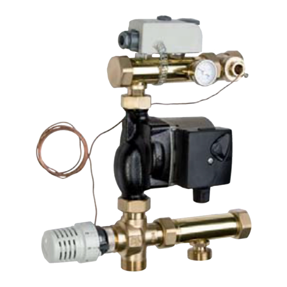
1. RANGE OF APPLICATION
The control unit UFH-PGKTA is developed for maintaini n g constant flow temperature in low-temperature radi-
ant heating systems. The flow temperature may be adjusted gradually between 20 and 70 °С, by means of the
thermostat. The limitation of the adjustment range is possible according to the maximum/minimum tempera-
ture. The temperature value can be read from the thermometer of the control unit.
The control unit is suitable for use in installations with combined panel heating/cooling and radiator heating. In
cooling operation the thermostatic head fully opens the 3-way-mixing valve and at the same time closes the
bypass. Thereby the flow temperature shall be controlled by the chiller (e.g. combined heat pump heat-
ing/cooling).
The control unit can be mounted either to the right or left of heating circuit manifolds with 1" male thread and
distance between supply and return branch of 210 mm. For that it is equipped with union nuts G 1".
The control unit has been designed for use in dry environments, e.g. in residential rooms, office spaces, and
industrial facilities. Usually the unit is installed in the central heating room or in a manifold cabinet.
Verify that the installation complies with existing regulations before operation to ensure proper use of the in-
stallation.
HENCO Industries NV • Toekomstlaan 27 - B-2200 Herentals • Tel. +32 14 28 56 60 • Fax +32 14 21 87 12 •
E
V
I
A
T
I
O
N
S
L
C
O
N
N
E
T
I
O
N
O
F
T
H
E
C
O
N
T
R
O
L
A
/
M
A
T
E
R
I
A
L
S
C
T
I
O
N
U
N
T I
en
Fig.1
1
2
4
4
4
4
6
6
6
6
7
7
7
7
8
www.henco.be
Advertisement
Table of Contents

Related Manuals for Henco UFH-PGKTA


Summary of Contents for Henco UFH-PGKTA
- Page 1 Verify that the installation complies with existing regulations before operation to ensure proper use of the in- stallation. HENCO Industries NV • Toekomstlaan 27 - B-2200 Herentals • Tel. +32 14 28 56 60 • Fax +32 14 21 87 12 • www.henco.be...
- Page 2 The correct installation of supply and return has to be ensured (Fig.2 and Fig.3.1 – 3.4). HENCO Industries NV • Toekomstlaan 27 - B-2200 Herentals • Tel. +32 14 28 56 60 • Fax +32 14 21 87 12 •...
- Page 3 Shut-off valves (recommendable) Chiller Zone valve Reversible heat pump (heating and cooling) Fig.4 Hydraulic switch HENCO Industries NV • Toekomstlaan 27 - B-2200 Herentals • Tel. +32 14 28 56 60 • Fax +32 14 21 87 12 • www.henco.be...
- Page 4 Also read the instructions on flushing as outlined in the installation/operating instructions for the heating circuit manifold. HENCO Industries NV • Toekomstlaan 27 - B-2200 Herentals • Tel. +32 14 28 56 60 • Fax +32 14 21 87 12 • www.henco.be...
- Page 5 2) The temperature set value can be protected against inadvertent manipulation using the tamper-proof cover HENCO Industries NV • Toekomstlaan 27 - B-2200 Herentals • Tel. +32 14 28 56 60 • Fax +32 14 21 87 12 • www.henco.be...
- Page 6 HENCO Industries NV • Toekomstlaan 27 - B-2200 Herentals • Tel. +32 14 28 56 60 • Fax +32 14 21 87 12 • www.henco.be...
Need help?
Do you have a question about the UFH-PGKTA and is the answer not in the manual?
Questions and answers