Table of Contents
Advertisement
Quick Links
ALBORZ
MICROSYSTEM
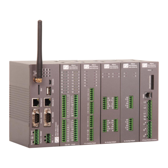
AMS-R4000 RTU
Modular Remote Terminal Unit
Alborz Micro System
SCADA Software
Provider
Power Distribution
Panel
Wireless Radio
Modem
Design and
Production of RTU &
HMI
Alborz MicroSystem
3'rd floor, No. 8, Zare St, Azadi
Ave, Tehran, IRAN
+98-21-66431719
+98-28-32243671
Info@alborzmicrosystem.com
+98-933-8785756
Advertisement
Table of Contents

Subscribe to Our Youtube Channel
Related Manuals for AMS AMS-R4000 RTU

Summary of Contents for AMS AMS-R4000 RTU
- Page 1 Alborz Micro System SCADA Software Provider Power Distribution Panel Wireless Radio Modem Design and Production of RTU & ALBORZ MICROSYSTEM AMS-R4000 RTU Alborz MicroSystem 3’rd floor, No. 8, Zare St, Azadi Modular Remote Terminal Unit Ave, Tehran, IRAN +98-21-66431719 +98-28-32243671 Info@alborzmicrosystem.com +98-933-8785756...
- Page 2 Information provided in this manual is intended to be accurate and reliable. However, AMS assumes no responsibility for its use, or for any infringements on the rights of third parties that may result from its use.
-
Page 3: Table Of Contents
AMS-R4000 RTU User’s Manual Table of Contents 1. Introduction 1.1. Overview 1.2. Package Checklist 1.3. Available Products 1.4. Product Specification 1.5. Physical Dimension 1.6. LED Indicators 2. Initial Setup 2.1. System Architecture 2.2. Installing Modules on a DIN Rail 2.3. - Page 4 AMS-R4000 RTU User’s Manual...
-
Page 5: Overview
AMS-R4000 RTU User’s Manual 1.1. Overview The AMS-R4000 is a modular Remote Terminal Unit (RTU) based on the high performance Cortex-A8 1GHz ARM CPU with 512MB of RAM and 4GB of Flash. The device has an internal 3G/4G cellular modem, two 10/100 base-T Ethernet port, four serial communication ports and a wide range of digital/analog input and output modules. -
Page 6: Available Products
AMS-R4932: 16 Channels Isolated Digital Input + 16 Channels Digital Output Module AMS-R4920: 8 Channels Analog Input Module (16 Bit Resolution with V / I Selection) + 8 Channels Isolated Digital Input + 4 Channels Relay Output + 2 Channel Temperature... -
Page 7: Product Specification
AMS-R4000 RTU User’s Manual 1.4. Product Specifications System CPU: Cortex-A8 based CPU, 32-bit/ 1GHz Instruction Execution Speed: 2000 MIPS RAM: 512MB Flash: 4 GB External Storage: Up to 32GB Micro SD Card I/O Scan Time: Adjustable (Minimum Time: 5 mS / Module) ... - Page 8 AMS-R4000 RTU User’s Manual Supported Protocols DNP3.0 Master/Slave IEC60870-5-101 Master/Slave IEC60870-5-103 Master IEC60870-5-104 Slave IEC61850 Server SNMP Modbus TCP Server/Client Modbus RTU Master/Slave OPC UA Server (DA, AE, HDA) Interface ...
-
Page 9: Physical Dimension
AMS-R4000 RTU User’s Manual 1.5. Physical Dimensions CPU Module Dimension (Unit: mm) - Page 10 AMS-R4000 RTU User’s Manual IO Module Dimension (Unit: mm)
-
Page 11: Led Indicators
AMS-R4000 RTU User’s Manual 1.6. LED Indicators CPU Module LED Groups LED (Color) Function Description PWR (Green) Light on, Device powered RUN (Blue) Blinking, Runtime Operation Blinking, Runtime Error ERR(Red) Light on, Exception Error System LED 200ms On/ 1800ms Off, Network searching... - Page 12 AMS-R4000 RTU User’s Manual...
-
Page 13: System Architecture
2.1. System Architecture The AMS-R4000 consists of a CPU module which is operates as the brain of the system. The CPU module manages the I/O module operation, collects their information and reports the processed information to the master of the SCADA system. -
Page 14: Installing Modules On A Din Rail
AMS-R4000 RTU User’s Manual 2.2. Installing Modules on a DIN-Rail CPU Module In order to installing the CPU module on a DIN-Rail, simply perform the following steps: Insert the top of the DIN-Rail bracket into the top of the DIN-Rail. - Page 15 AMS-R4000 RTU User’s Manual After performing these steps, CPU modules installation is completed. I/O Modules In order to installing the I/O module on a DIN-Rail besides the other modules, simply perform the following steps: Insert the top of the DIN-Rail bracket into the top of the DIN-Rail.
- Page 16 AMS-R4000 RTU User’s Manual Rotate the top of the module downwards until the bracket snap into the DIN-Rail. After performing these steps, IO module installation is completed. Connectors In order to installing the module connectors, simply perform the following steps:...
- Page 17 AMS-R4000 RTU User’s Manual If it is the first I/O module, use the AMS-R4001 expansion connector in order to communicate between the CPU and I/O module. If it is not the first I/O module, use AMS-R4002 expansion connector in order to communicate...
-
Page 18: Removing Modules From A Din Rail
AMS-R4000 RTU User’s Manual After performing these steps, installation is completed. 2.3. Removing Modules from a DIN-Rail In order to removing the CPU and I/O module from a DIN-Rail, simply perform the following steps: Remove the expansion connector between modules. - Page 19 AMS-R4000 RTU User’s Manual Use a screwdriver in order to push down the spring-loaded part of the bracket. Rotate the bottom of the module upwards and then remove it from the DIN-Rail.
-
Page 20: Connecting The Module Power
2.4. Connecting the Module Power The AMS-R4000 CPU module accepts power in the range of 9-36V DC. It should be noted that the I/O modules do not need the separate input power and the required power of these modules is provided by the CPU module through the expansion connector. -
Page 21: Factory Defaults
AMS-R4000 RTU User’s Manual 2.7. Factory Defaults If the device network configuration was forgotten or the device booting failed due to the wrong user programming, simply perform the following steps in order to reset the device to the factory defaults: ... - Page 22 AMS-R4000 RTU User’s Manual...
-
Page 23: Digital Input Modules
AMS-R4000 RTU User’s Manual 3.1. Digital Input Modules Overview The AMS-R4000 RTU provides two types of the digital input modules. The AMS-R4116/ AMS-R4132 supports 16/32 channels of isolated digital inputs. To simplify field wiring, each four inputs of these modules are building a group with a common return. - Page 24 AMS-R4000 RTU User’s Manual Wiring Diagram...
-
Page 25: Digital Output Modules
3.2. Digital Output Modules 3.2.1. Transistor Output Overview The AMS-R4000 RTU provides two types of the transistor digital output modules. The AMS-R4216 supports 16 channels of transistor digital outputs and the AMS-R4232 supports 32 channels of transistor digital outputs. Using transistor instead of mechanical relay in these modules provide a fast performance and longer lifetime. - Page 26 AMS-R4000 RTU User’s Manual Wiring Diagram Max Load per Channel 1W Max Load power per Channel is 1W...
- Page 27 AMS-R4000 RTU User’s Manual 3.2.2. Relay Output Overview The AMS-R4000 RTU provides a type of the relay digital output module. The AMS-R4216R supports 16 channels of relay digital outputs it can be used to control relays, solenoid valves, panel lamps and other on/off devices which supplied with DC or AC source.
- Page 28 AMS-R4000 RTU User’s Manual Wiring Diagram...
-
Page 29: Analog Input Modules
3.3. Analog Input Modules Overview The AMS-R4000 RTU provides four types of the analog input modules. The AMS-R4308 supports 8 channels of analog inputs, the AMS-R4312 supports 12 channels of analog inputs, the AMS-R4316 supports 16 channels of analog inputs and the AMS-R4324 supports 24 channels of analog inputs. The modules can be used to monitor level, flow, pressure, temperature and other analog transmitters. - Page 30 AMS-R4000 RTU User’s Manual Specifications AMS-R4308: 8 Channels Analog Input Module AMS-R4312: 12 Channels Analog Input Module AMS-R4316: 16 Channels Analog Input Module AMS-R4324: 24 Channels Analog Input Module Parameters Value AMS-R4308: 8 Channels (V/I Selectable) AMS-R4312: 12 Channels...
- Page 31 Wiring Diagram Note: As you can see in the above figure, the AMS-4308 EM the AMS-4316 EM Modules support both of the is not current and Voltage input mode. It should be noted that if each one of the input channels of the device...
-
Page 32: Analog Output Modules
The modules have 4 / 8 LEDs to indicate the signal state and check loop at the outputs. The required power of these modules are supplied by the expansion connector from the AMS-R4000 CPU module. - Page 33 AMS-R4000 RTU User’s Manual Specifications AMS-R4404: 4 Channels Analog Output Module AMS-R4408: 8 Channels Analog Output Module Parameters Value AMS-R4404: 4 Channels Outputs per Module AMS-R4408: 8 Channels Output Type Voltage, Current Voltage Output Range 0 to 5 V, 0 to 10 V, -5 to +5 V,...
-
Page 34: Thermocouple Modules
AMS-R4000 RTU User’s Manual 3.5. Thermocouple Modules Overview The AMS-R4000 RTU provides two types of the precise and high performance thermocouple input modules. The AMS- R4504 supports 4 channels of thermocouple inputs and the AMS-R4508 supports 8 channels of thermocouple inputs. The... - Page 35 52.18 Constantan Copper -200°C to +400°C -55°C to +125°C (0°C to +400°C) Specifications AMS-R4504: 4 Channels Thermocouple Input Module AMS-R4508: 8 Channels Thermocouple Input Module Parameters Value AMS-R4504: 4 Channels Inputs per Module AMS-R4508: 8 Channels Input TC Type K, J, N, R, S, T, E, B, …...
- Page 36 AMS-R4000 RTU User’s Manual Options and Accessory AMS-R4504: 4 Channels Thermocouple Input Module AMS-R4508: 8 Channels Thermocouple Input Module Parameters Value Digital Sensor Input Capability 2 Channels DS18B20 stainless still Waterproof Digital Sensor DS18B20 Environmental sensor Wiring Diagram Warning Do no plug in or plug out the digital sensors when the device is powered up.
- Page 37 The AMS-R4000 RTU provides two types of the platinum resistance temperature detector (RTD) input modules. The AMS-R4604 supports 4 channels of RTD and the AMS-R4608 supports 8 channels of RTD. The modules benefit from a precise Delta-sigma Analog to Digital Converter (ADC) in order to measure temperature from both of the PT100 and PT1000 sensor.
- Page 38 The device is able to transfer the measuring parameters to a Modbus master device through the RS-485 serial port and the AMS bus. By using this feature, AMS-R4701 can be communicating with two masters simultaneously. One of the masters is AMS-R4000 RTU CPU module and another can be standard Modbus...
- Page 39 Auxiliary supply 85~280 VAC / 9 – 36 VDC MODBUS RTU Protocol through RS485 serial port. Communication AMS-4000 CPU Communication through AMS Bus Operating temperature: -10 °C to 60 °C Environmental Storage temperature: -25 °C to +70 °C Humidity 5% to...
- Page 40 Required power of the AMS-4701 module is provided by the AMS-R4000 CPU module through the expansion connector. But if you want to use the AMS-4701 module separately, you should provide the required power of the module by connecting an 85~280VAC supply to "Vs" and "Vn" pins.
- Page 41 AMS-R4000 RTU User’s Manual Press Enter button to Press up or down see the parameter type button to navigate of the shown value. in the pages. Press Enter button to see the parameter type of the shown value.
- Page 42 AMS-R4000 RTU User’s Manual By reusing the up or down button, you can switch between other pages which shown the line voltages, active, reactive and apparent power, active, reactive and apparent energy, power factor and frequency as shown below:...
- Page 43 AMS-Bus or the Modbus communication. Port1 shows the communication status through the Modbus RTU over RS485 connection and Port2 shows the communication status through AMS Bus with AMS- R4000 RTU. If the request and respond packet exceed than 9999...
-
Page 44: Reserved Modules (Load Cell
8 channels of digital input, 2 channels of temperature sensor (DS18B20) and 4 channels of digital relay output. The AMS-R4932 supports 16 channels of digital input and 16 channels of transistor digital output. For more detail about analog input please see the AMS-R4308 specification table... - Page 45 Wiring Diagram Note: As you can see in the above figure, the AMS-4920 EM Module supports both of the current and Voltage is not connected to your input mode. It should be noted that if each one of the input channels of the device Transducer or Sensor, simply do a wire jumping between V &...
- Page 46 AMS-R4000 RTU User’s Manual...
- Page 47 4.1. Quick Start Start with console cable To start programming with AMS-R4000 RTU, all you need is a USB console cable which is placed in package of device. Connect RTU to standard 9-36 VDC power supply. Wait until the device startup complete which takes about 30 second.
- Page 48 Copyright © 2017 AMS Co. AMS reserves the right to make changes to specifications of products described at any time without notice and without obligation to notify any person of such changes. Weight and dimensions are approximate. AMS Series’ are either trademarks or registered trademarks of AMS. Other names or products not mentioned may be registered trademarks or trademarks of the company.
Need help?
Do you have a question about the AMS-R4000 RTU and is the answer not in the manual?
Questions and answers