
Related Manuals for Eastern Tabletop 2800

Summary of Contents for Eastern Tabletop 2800
- Page 1 Toll Free: (888) 422-4142 OUTDOOR PORTABLE PATIO HEATERS PROVIDE A WARM EXPERIENCE FOR YOUR GUEST UNDER THE STARS. MODEL #2800 INSTRUCTION MANUAL Keep the instructions for future reference...
- Page 2 WARNlNG SAFETY RULES PLEASE READ THE FOLLOWING SAFETY RULES PRlOR TO OPERATION OF THE HEATER FOR YOUR SAFETY If you smell gas: 1.Shut off gas to the appliance. 2. Extinguish any open flame. 3.If odor continues, immediately call your gas supplier or your fire Department.
- Page 3 warning Read the instructions before installation and use. -This appliance must be installed and the gas cylinder stored in accordance with the regulations in force; -Do not obstruct the ventilation holes of the cylinder housing; -Do not move the appliance when in operation; -Shut off the valve at the gas cylinder or the regulator before moving the appliance;...
-
Page 4: Table Of Contents
TABLE OF CONTENTS Caution ………………………………………………………. Heater Stand and Location ………………………………… 2 Gas Requirements ………………………………………….. 2 Leakage Test ………………………………………………… 2 Operation and Storage ……………………………………... 3 Cleaning and Care ………………………………………….. 4 Parts and Specifications ..………………………………….. 4 Assembly Parts and Procedures ………………………….. 6 Problems Check List ………………………………………... -
Page 5: Caution
CAUTION PLEASE READ CAREFULLY THE FOLLOWING SAFETY GUIDELINES BEFORE OPERATION. Do not use the patio heater for indoors, as it may cause personal injury or property damage. This outdoor heater is not intended to be installed on recreational vehicles and/or boats. Installation and repair should be done by a qualified service person. -
Page 6: Heater Stand And Location
HEATER STAND AND LOCATION The heater is primarily for outdoor use only. Always ensure that CEILING adequate fresh air ventilation is provided. Always maintain proper clearance to non protected combustible materials i.e. top 100 cm and sides 100 cmminimum. Heater must be placed on level firm ground. Never operate heater in an explosive atmosphere like in areas where gasoline or other flammable liquids or vapors are stored. -
Page 7: Operation And Storage
maximum Warning:check that no broken on the glass is found before operation. Off: the heater stop work Hi: maximum temperature position Lo: minimum temperature position lgniter Igniter Variable control knob regulator... -
Page 8: Cleaning And Care
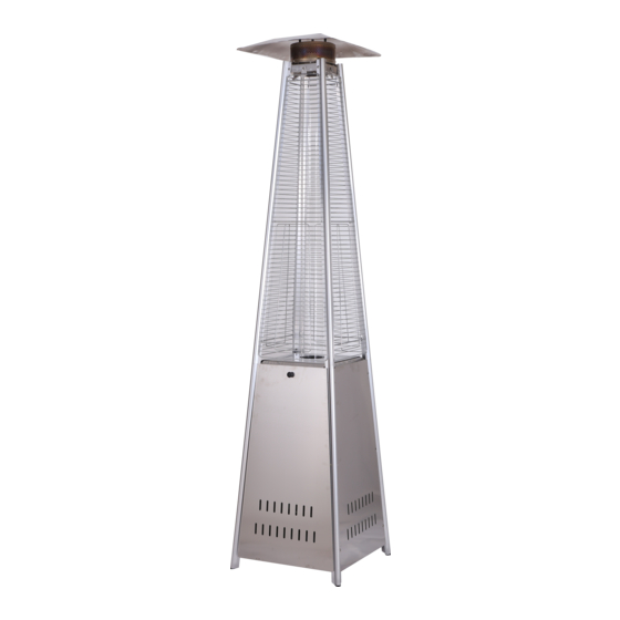
600 mm Reflector Glass Tube Protective Guard Upper Support Front Panel Side Panel Lower Support Bottom plate Wheel Assy 660 mm - 4 -... - Page 9 A. Construction and characteristics Transportable terrace/garden heater with tank housing Casing in steel with powder-coating(BSH-B) or in stainless steel(BSH-A). Gas hose connections with metal clamp (screw caps for Germany) Heat emission from reflector B. Specifications Use propane,butane or their mixtures gas only. Max.
-
Page 10: Assembly Parts And Procedures
ASSEMBLY PARTS Tools needed: Philips screwdriver w/ medium blade Spray bottle of soap solution for leakage test Parts List: Item # Description/Part # Qty Picture Comments Control Box Assy Includes: Burner,Pilot,Valve Assy, Pilot Tube,Igniter, Control Knob, Tip Switch Wheel Assy Bottom plate Lower Support Upper Support... - Page 11 ASSEMBLY PARTS Parts List: Item # Description/Part # Qty Picture Comments Side Panel A chain will be attached to the Front Panel Front Panel Propane Regulator Hose Will be attched to the Upper Support Block Belt Screw M5 x 12mm Wing nut Will be attched to the Stud...
- Page 12 ASSEMBLY PROCEDURES STEP 1 1-1. Insert the pin of bottom plate (3) to the lower holes of lower support (4). 1-2. Insert the pin of control box assy (1) to the upper holes of lower support. Note: The side of control box assy which has the magnet should be the same side of bottom plate which has the holes for front panel.
-
Page 13: Problems Check List
STEP 3 Screw M5 X 12 3-1. Assembly the top plate (6). Insert the pin of top plate to the upper hole of upper support. 3-2. Secure the top plate, control box assy and bottom plate with 9pcs M5X12 screw. STEP 4 Bolt M6 X 10 Assemble the wheel assy (2) to the bottom plate using... - Page 14 STEP 5 Screw M5 X 12 Secure the block belt (15) to the lower supports with 2pcs M5x12 screws (16). STEP 6 Install the glass tube(7). Carefully install the glass tube between central of top plate and control box assy. Make sure to place the lower end of the glass tube between the three clips on the control box assembly.
- Page 15 STEP 7 Screw M5 X 12 7-1. Assembly the damper (8). Put the damper on the quartz tube, press it and make sure the ceramic fibre in the damper is in the outside of quartz tube. 7-2. Secure the damper with 3pcs M5X12 screws (16). STEP 8 Screw M5 X 12 Install 2pcs side panels (12) with 8pcs M5x12 screws.
- Page 16 STEP 9 Screw M4 X 10 Knob Nut M4 wafer Chain Assemble the chain (25) and wafer (26) to the inside of front panel (13) with M4x10 screw (23) and M4 nut (22) and then install the knob (24) to M4x10 screw. Hang the chain to the hole on the control box assembly and attach the pothook on front panel to the holes of bottom plate.
- Page 17 STEP 11 Screw M5 X 12 Fixing Bracket 11-1. Insert the mesh (11) on the top plate. Align the holes to the holes of top plate. 11-2. Secure the mesh on the top plate with 3pcs M5X12 screws and 3pcs fixing brackets (20). STEP 12 Wing nut Small flat...
- Page 18 STEP 13 Ensure the hose does not contact any high temperature surfaces, or it may melt and leak WARNING! STEP 14 WARNING! of the gas system is replaced. WARNING! erty, serious bodily injury, or death. manifolds and valves. If the leak cannot be stopped, Hose / Regulator connection Regulator / Cylinder...
- Page 19 PROBLEMS CHECK LIST PROBLEM PROBABLE CAUSE SOLUTION Pilot will not light Gas valve may be OFF Turn the gas valve ON Tank fuel empty Refill LPG tank Opening blocked Clean or replace opening Air in supply system Purge air from lines Loose connections Check all fittings Pilot will not stay on...
Need help?
Do you have a question about the 2800 and is the answer not in the manual?
Questions and answers